 CIANA 48V · Installation guide
enlighten.biz/ciana-48v-install
CIANA 48V · Installation guide
enlighten.biz/ciana-48v-install
Installation guide
CIANA 48V magnetic track, installed.
The surface and recessed channels, from a bare ceiling to a lit luminaire, in four stages. Written for the electrician on site: print it and take it up the ladder.
Fitting the slimmer CIANA Elance' 6mm track instead? That system goes together differently and has its own guide.
Before you start
Twelve rules. Every one of them is a call-back avoided.
- Install to local and national electrical regulations, and only by a licensed electrician who knows how the system goes together.
- Isolate the circuit at the distribution board before anything is touched, and prove it dead.
- The luminaires run on 48V DC. Never connect one, or a length of track, to the mains — it destroys the fitting on the spot.
- Set the run out on the ceiling from the lighting layout before the first hole is drilled. The channel comes in 1, 2 and 3m lengths; other lengths are made to order.
- Check what the ceiling can carry. The fixings have to hold the track, its luminaires and the supply.
- Indoors only, and dry. The system is rated to a maximum operating temperature of 70°C.
- Add up the luminaire wattage on the run before choosing the supply, and load the supply to about 80% of its rating. Eight 10W heads is 80W, so specify the 100W supply.
- Keep a jointed run to about 5m in one group. Longer runs have been installed, but past that voltage drop starts to show as a brightness difference between the first luminaire and the last — feed a longer ceiling as more than one run.
- Every powered joint carries the supply across as well as holding the track in line. A module that is not fully home leaves everything past it dark.
- Surface track takes three fixings in every metre. Drive all of them — the channel is only straight once the whole length is drawn tight to the ceiling.
- The LED module is not replaceable on site. A failed luminaire is swapped, never opened.
- Black is the standard body finish. White is a custom finish at extra cost — confirm it on the order before the track goes up.
The parts
Two channels carry the same luminaires. Everything else on the run is chosen to match whichever one is going up.
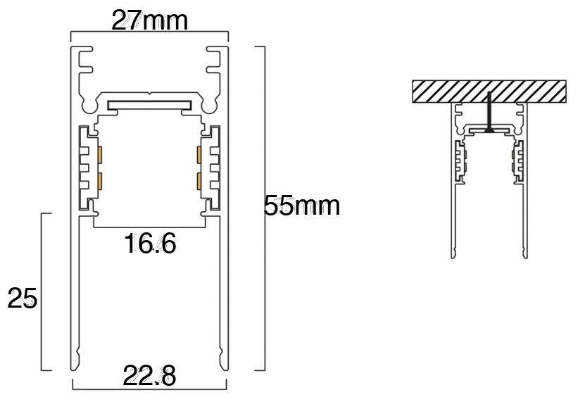
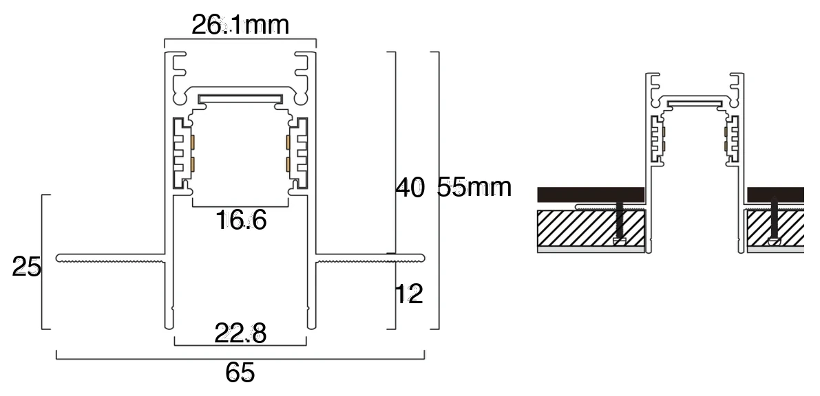
| Part | Code | What it does |
|---|---|---|
| Surface channel | EN-MGTS | 27 × 55mm, in 1, 2 and 3m. |
| Recessed channel | EN-MGTR | 65 × 55mm, in 1, 2 and 3m. Needs a 27–30mm slot. |
| Hanging kit | EN-MGTS-Hanging Kit | Suspends the surface channel on 2m wires. |
| Corner connector, horizontal | EN-MGCS-HH · EN-MGCR-HH | Turns the run in the plane of the ceiling. |
| Corner connector, vertical | EN-MGCS-HV · EN-MGCR-HV | Takes the run from ceiling to wall. |
| Jointer | EN-MG-Jointer | Holds two lengths in line. Mechanical only — no power passes through it. |
| Straight module | EN-MG-Straight Module | Carries 48V from one length to the next. |
| Straight module with wire | EN-MG-Straight Module w/ Wire | The same connection on a flying lead, where two lengths cannot meet. |
| Corner module | EN-MG-Corner Module | Carries 48V across an angle. |
| Input module | EN-MG-Input Module | Brings an external supply in on four wires. Also the route DALI-2 arrives by — how to wire it for DALI. |
| Integrated supply | EN-MG48VPS | 100, 200 and 300W at 48V, sitting on the track itself. On a DALI run, wire it this way. |
| End cap | Comes with the channel | Closes the end of the run over the supply, with the supply's lead passing through it. |
Prices, sizes and the rest of the system are on the CIANA 48V page.
Stage 1
Fix the track
Surface goes onto a finished ceiling in an afternoon. Recessed has to be built into the ceiling before it is closed, so it belongs in the ceiling programme, not the lighting one.
Surface · EN-MGTS
Screwed straight to the soffit through the floor of the channel. Three fixings in every metre.
01
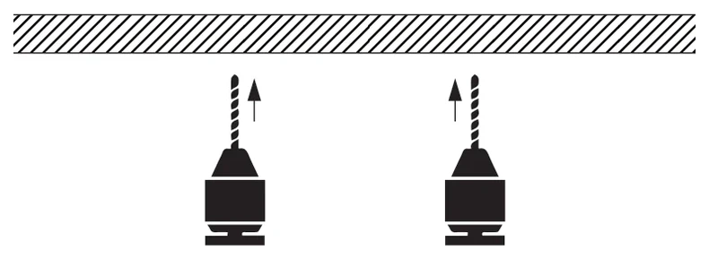
Mark and drill
Set the run out on the ceiling from the layout, then drill at the track's own fixing holes, sized to the plastic anchors.

02
Set the anchors
Push an anchor into every hole and tap it flush. Any hole left out now is a fixing missing later.
03
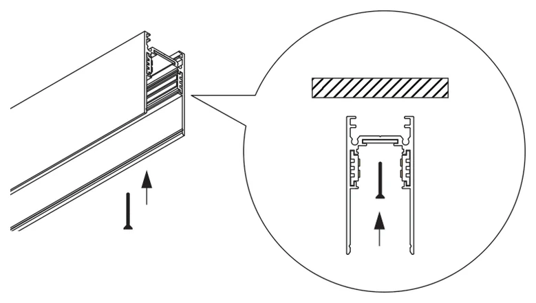
Screw the first length up
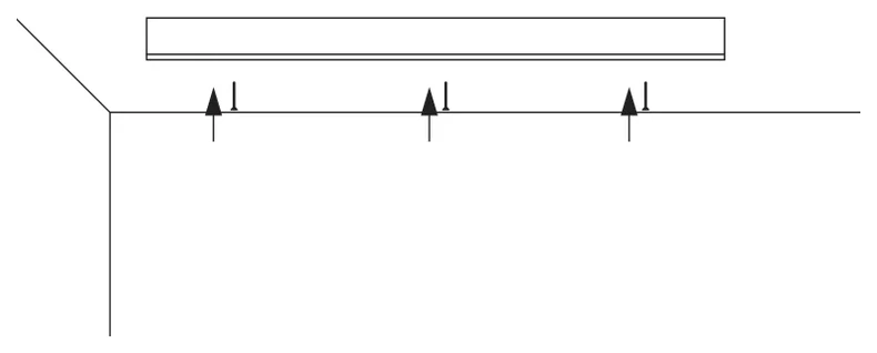
Offer the channel to the line and drive the screw up through the floor of the track into the anchor. The detail shows it passing up through the middle of the channel.
04
Work along the run
Three fixings in every metre, all the way to the end of the run. A 3m length takes nine.
05
Sight along it
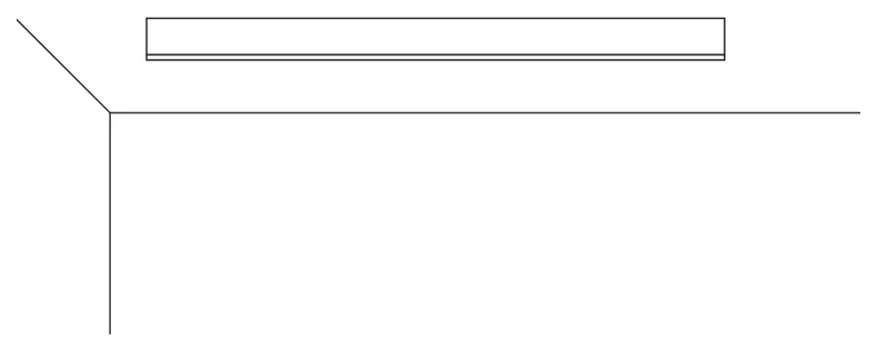
Look down the finished run before anything goes on it. A channel that is not straight shows as a kink in every luminaire that sits in it.
Recessed · EN-MGTR
Built into a channel formed in the ceiling, then boarded and skimmed up to the lip. Once the boarding is on, the track cannot be reached — everything is proved before that step.
01
Form the channel
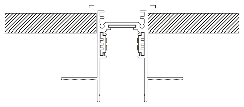
Build a plywood channel in the ceiling to the track's section and the shape of the run. It has to carry the track, the luminaires and the supply, and be deep enough to take the 55mm section. Cut the visible slot at 27–30mm.
02
Offer the track in
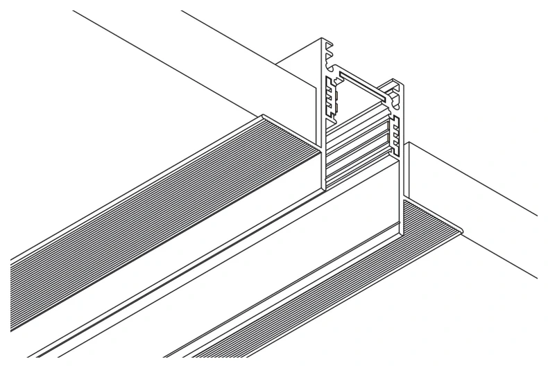
Set the channel into the opening and check the whole run end to end while it is still open.
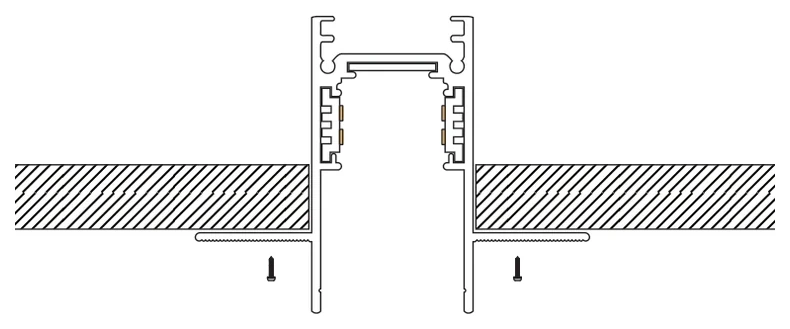
03
Fix through the flange
Screw up through the board into the track's flanges. Prove the wiring and test-fit a luminaire on every length now — this is the last moment the track is reachable.
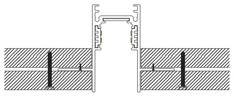
04
Board over the flange
Lay the outer board over the flanges and fix it. The flange is what the board closes onto; the aperture is what stays visible.
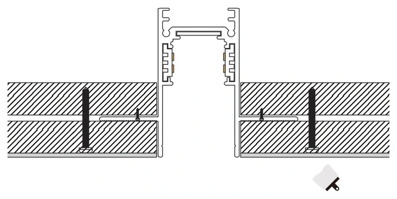
05
Skim and paint
Skim up to the lip of the channel and paint. Keep compound out of the channel: it sets on the copper strips and no luminaire will make contact afterwards.
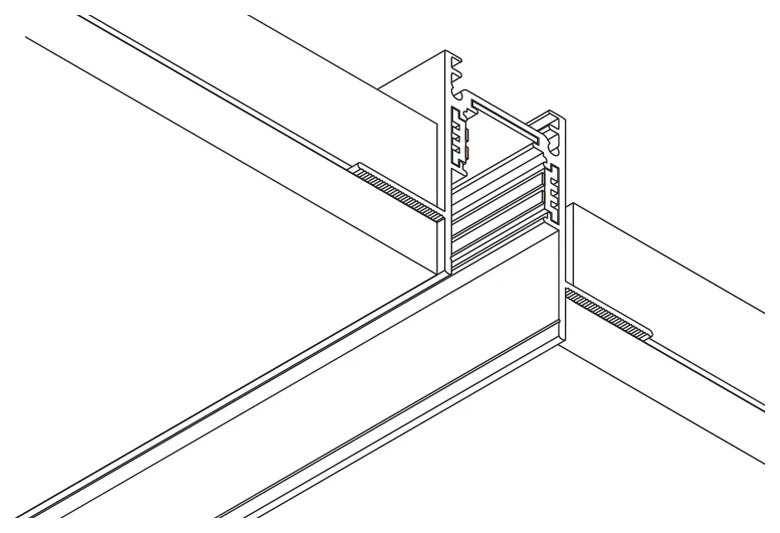
06
Flush
The finished run reads as a slot in the ceiling, with no visible frame.
There is a third mount: the hanging kit (EN-MGTS-Hanging Kit) suspends the same surface channel on 2m wires. Only the fixing at the ceiling changes — every stage after this one is the same.
Stage 2
Join the lengths
Two jobs, and they are separate: holding the run in line, and carrying the supply along it. The jointer does the first. The modules and the corners do the second.
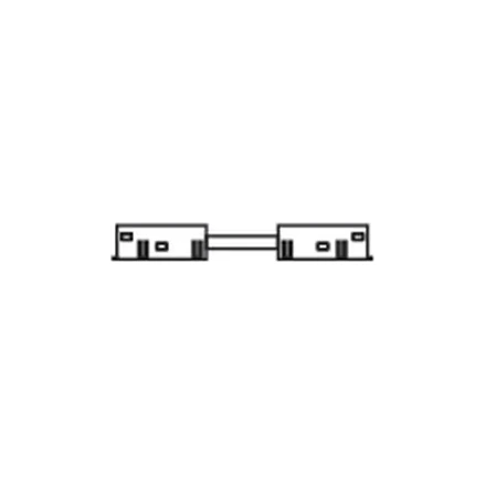
Straight module
Pushes into the end of both lengths and carries 48V across the joint. A wired version does the same where the two ends cannot meet.
EN-MG-Straight Module
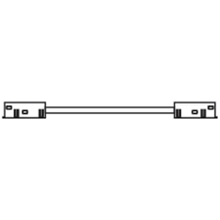
Corner module
The same connection on a longer lead, so the supply follows the run around an angle where a rigid link cannot.
EN-MG-Corner Module
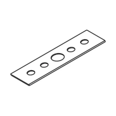
Jointer
A drilled plate that holds two lengths straight and level to each other. It carries no power — a joint with only a jointer in it leaves the next length dark.
EN-MG-Jointer
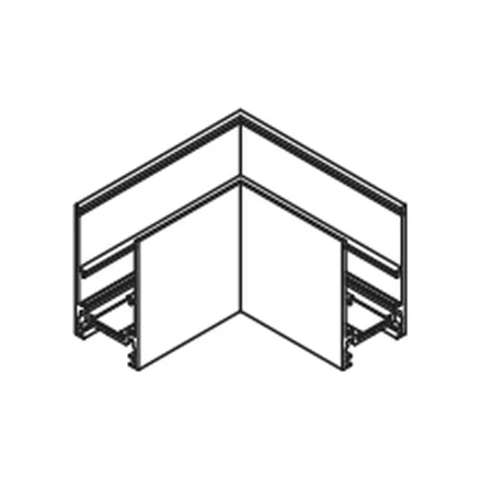
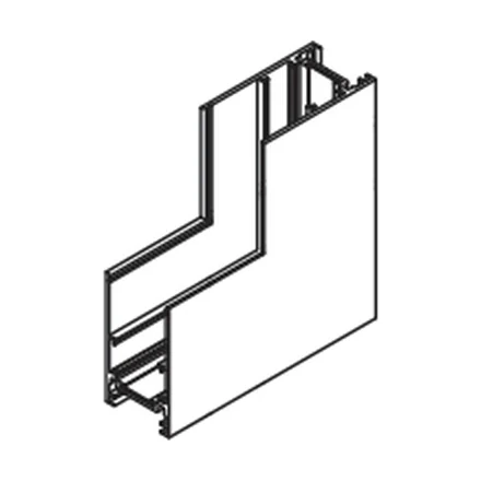
Horizontal corner · surface
Turns the run through a right angle in the plane of the ceiling, and carries the supply round with it.
EN-MGCS-HH
Vertical corner · surface
Takes the run off the ceiling and down the wall in one piece, with no break in the channel.
EN-MGCS-HV
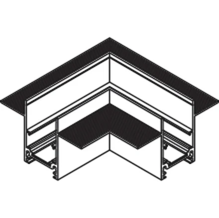
Horizontal corner · recessed
The same turn for the recessed channel, carrying the flange around the corner so the board closes onto it.
EN-MGCR-HH

Vertical corner · recessed
Ceiling to wall for the recessed channel. Both faces have to be formed and boarded before it goes in.
EN-MGCR-HV
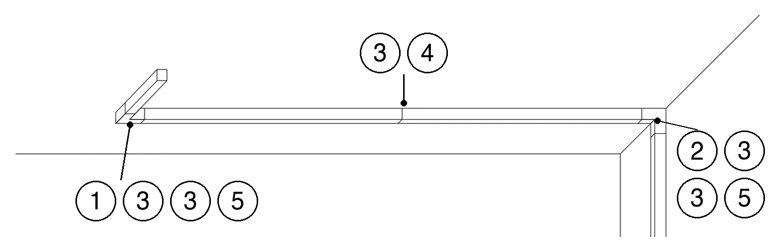
A corner connector replaces the ends of the two lengths it joins. Allow for it when the run is set out, or the last length arrives short.
Stage 3
Bring in power
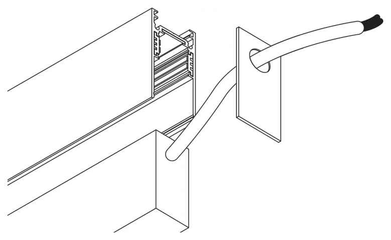
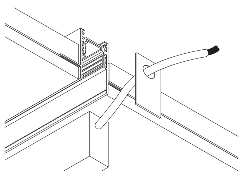
Power comes in at the end of the run, either from a supply that sits on the track or from one above the ceiling. The end cap closes that same end over the supply, with its lead passing through the cap. End caps come with the channel.
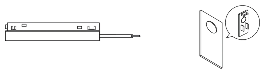
Option A
Supply on the track
The EN-MG48VPS slides into the end of the run and becomes part of it. Mains lands on its flying lead — three cores, line, neutral and earth, and all three are connected; 48V goes straight into the copper strips. Nothing else is needed.
100W is 225mm long, 200W is 265mm and 300W is 310mm — the supply adds that much to the run, so set it out together with the track.
Option B
Supply above the ceiling
Where the run has no length to spare, or where several runs share one supply, the supply sits in the ceiling void and its 48V output comes down to an EN-MG-Input Module at the end of the track. Its mains side is the same three cores: line, neutral and earth.
The input module is a four-wire connection, and it is the same one DALI-2 control arrives through. Wiring it for DALI, with either supply, is its own page: CIANA 48V on DALI.
Whichever is used, size it on the wattage actually on the run and leave headroom: about 80% loading is what the supply is specified for.
Stage 4
Mount the luminaires
Nothing is wired and nothing is screwed. Every head is held to the channel without tools and lit by the contacts that meet the copper strips, and it can be moved along the run at any time. The power strips carry the positive and negative of the 48V, but a head works fitted either way round — there is no wrong direction. Which of the three ways below applies is decided by the luminaire, not by the track.
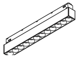
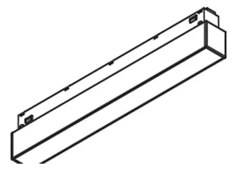
Heads that sit flush in the channel
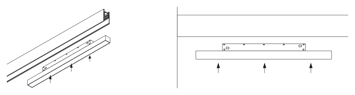
Push it home
Hold the head square under the channel and push its face straight up into the slot. The magnets take it the last few millimetres and it lights as the contacts meet.
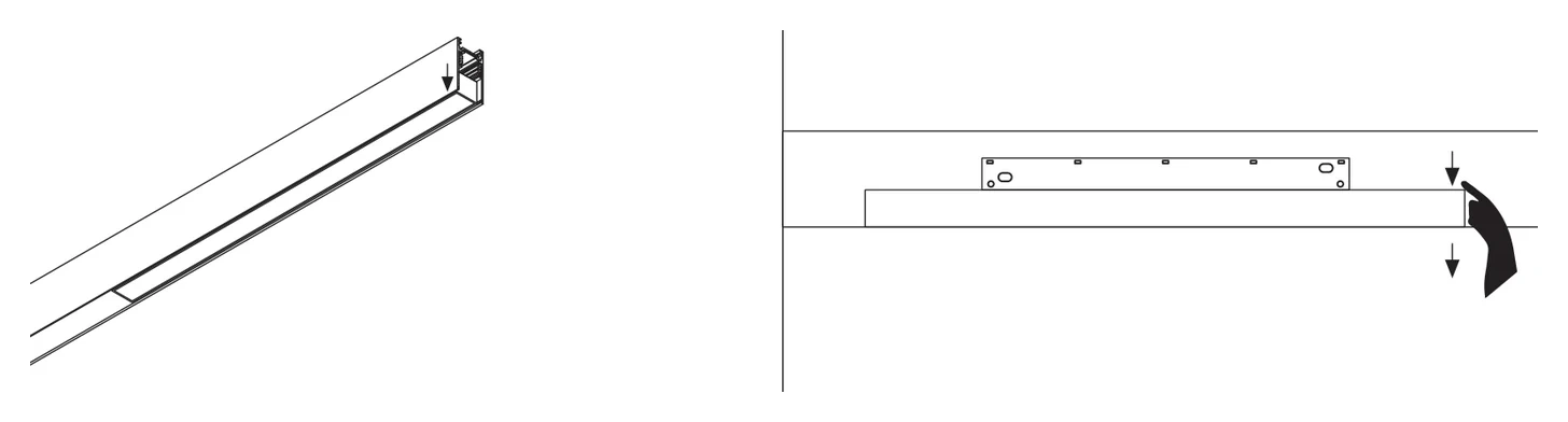
Pull one end free
To take it off, grip one end and pull it firmly away from the channel. It breaks away at that end and comes out.
Heads on a magnetic box
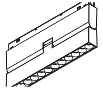
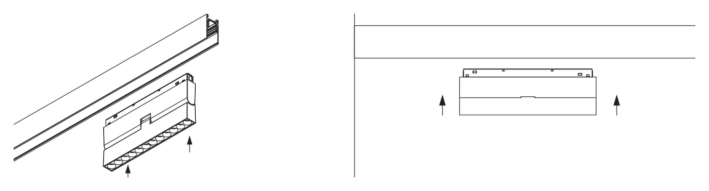
Push the box up
Press on the face of the magnetic box and push it up into the slot until it locks. The head lights as the box seats.
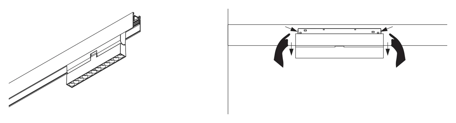
Press the button
This one is latched, so it will not come away on its own. Press the button on the side of the box to release the latch, then draw the head away from the channel.
Spotlights
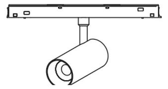
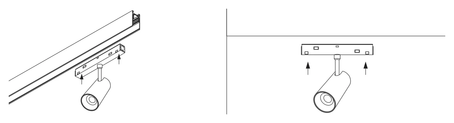
Seat it, then aim it
The spotlight sits on the same magnetic box: push the box up into the slot until it locks, then aim the head. Aiming does not disturb the box.
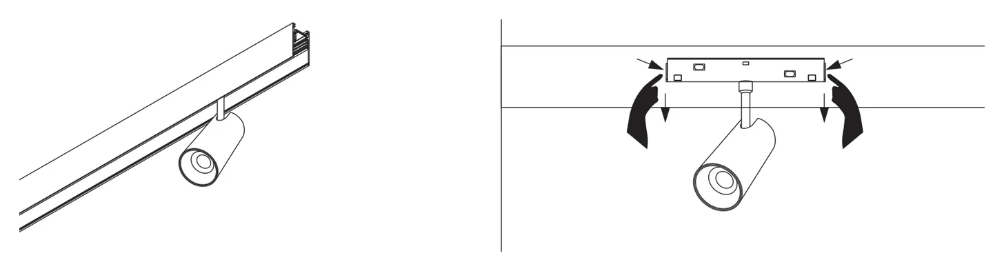
Same button to release
Press the side button and draw it away from the channel. Never pull a spotlight off by its barrel.
If a head is stiff going in, take it off and offer it up again square. Forcing one in at an angle marks the channel and can bend the contacts.
What mounts on it
Every head on the CIANA 48V system fits the surface and the recessed channel alike.
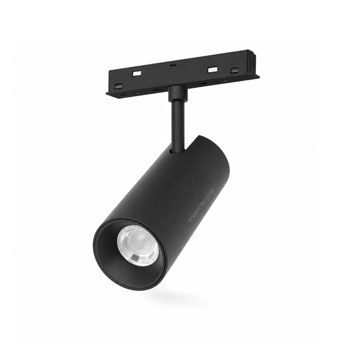
Spot Light
EN-MGTL · 7 / 12 / 20W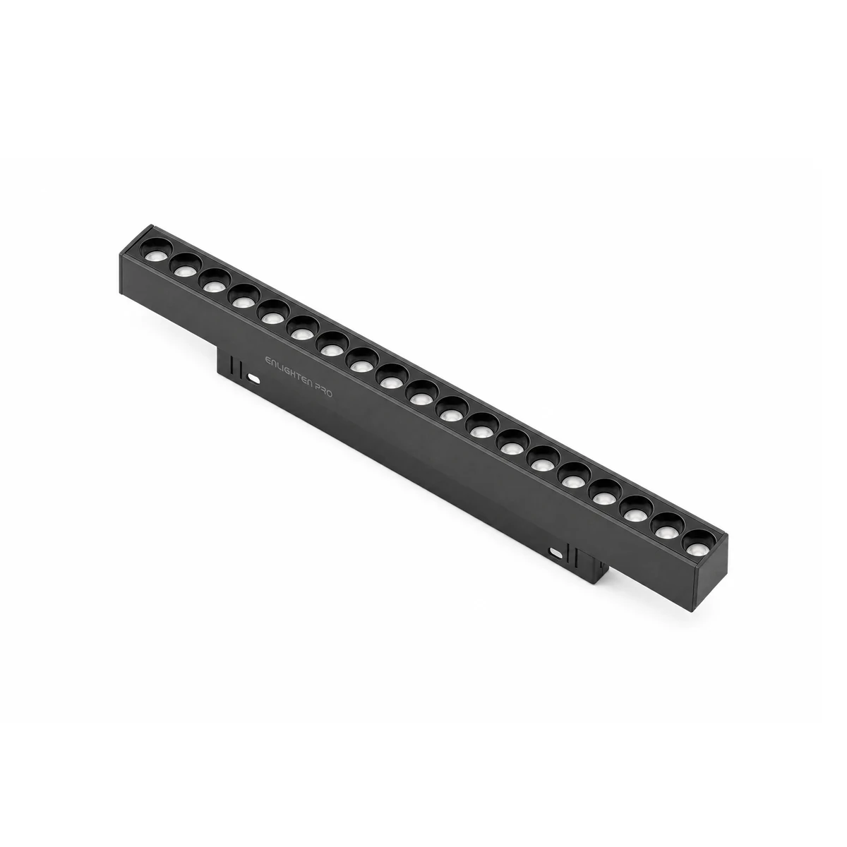
Laser Light
EN-MGLL · 6 – 30W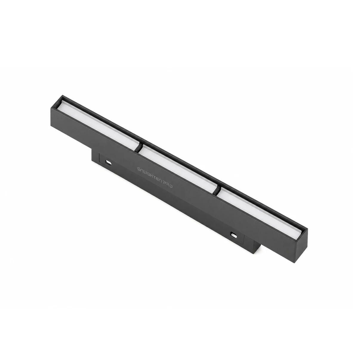
Wall Washer
EN-MGWW · 6 – 30W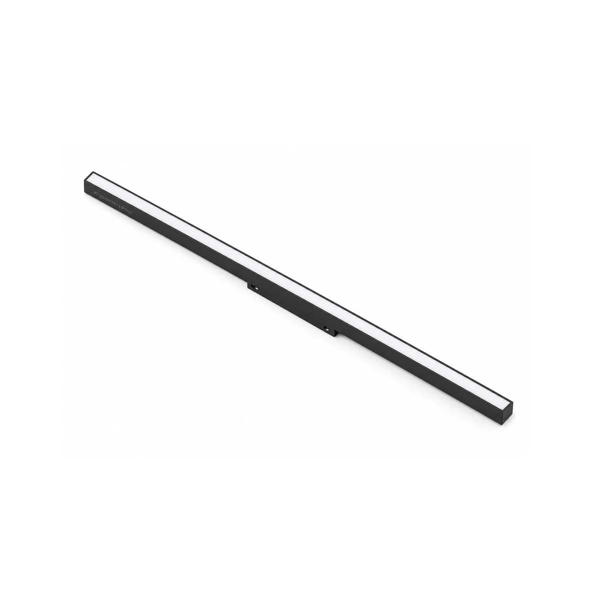
Diffused Linear Light
EN-MGLN · 10 – 40W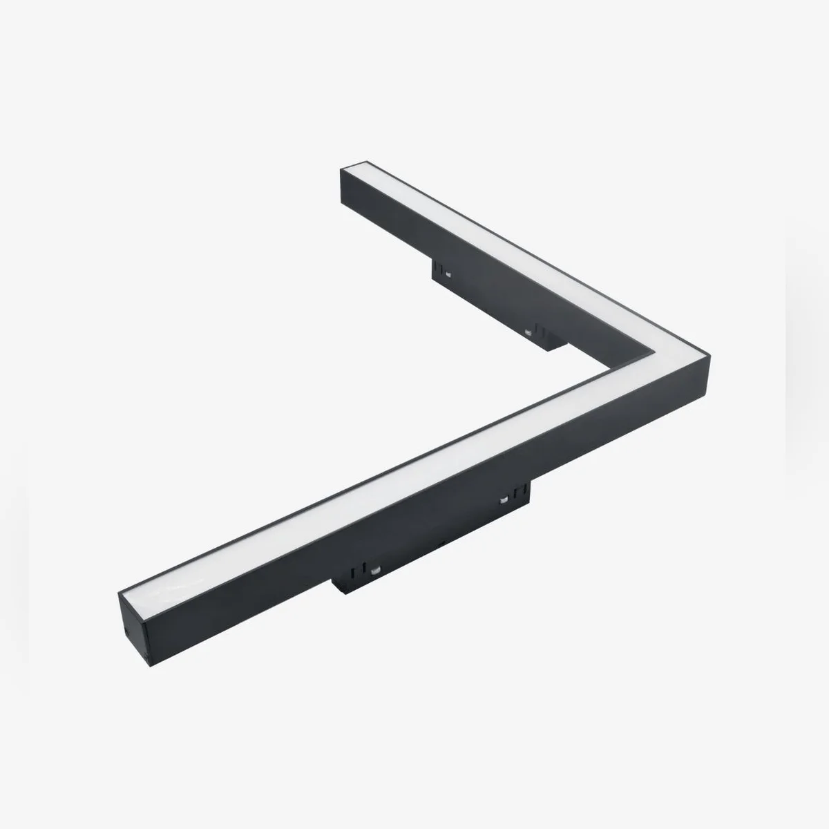
Corner Linear Light
EN-MGLN-C20 · 20W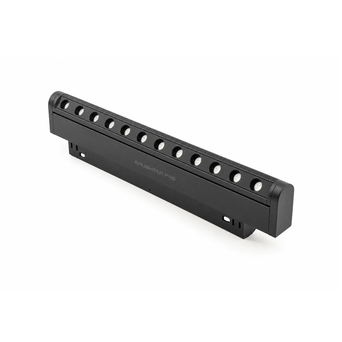
Rotatable Laser Light
EN-MGLLR · 6 / 12W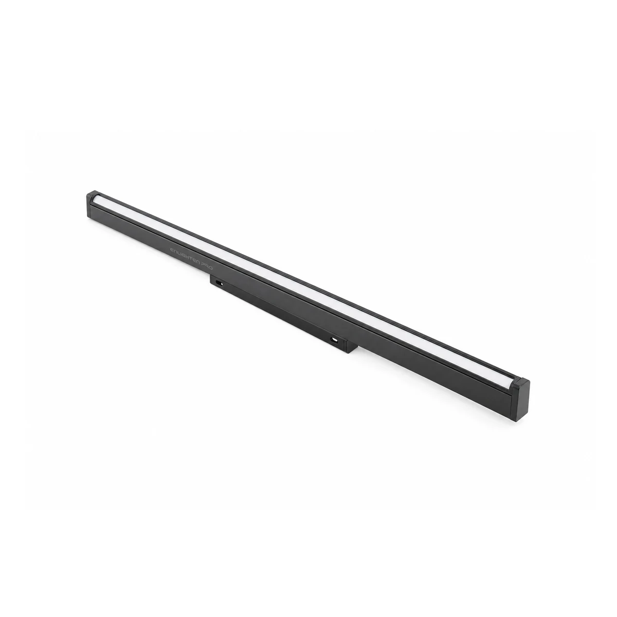
Rotatable Linear Light
EN-MGLNR · 10 / 20W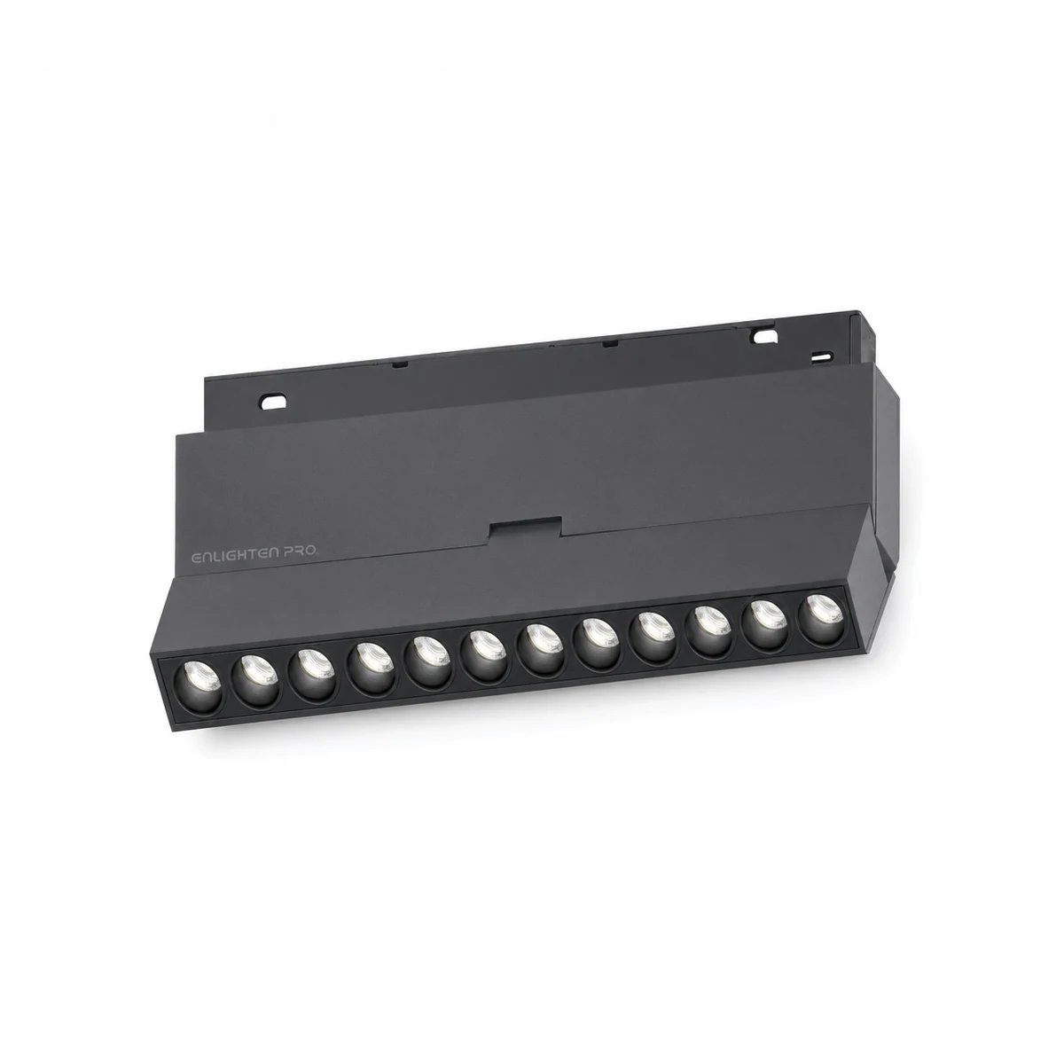
Tiltable Laser Light
EN-MGLLT · 6 / 12 / 18W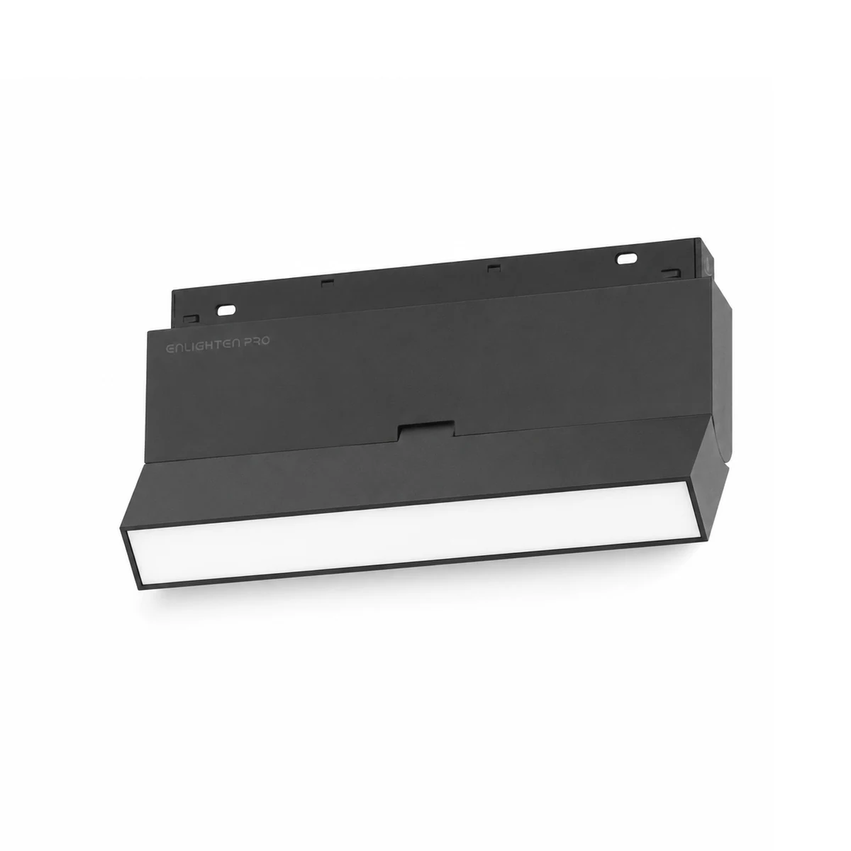
Tiltable Linear Light
EN-MGLLTD · 6 / 12 / 18W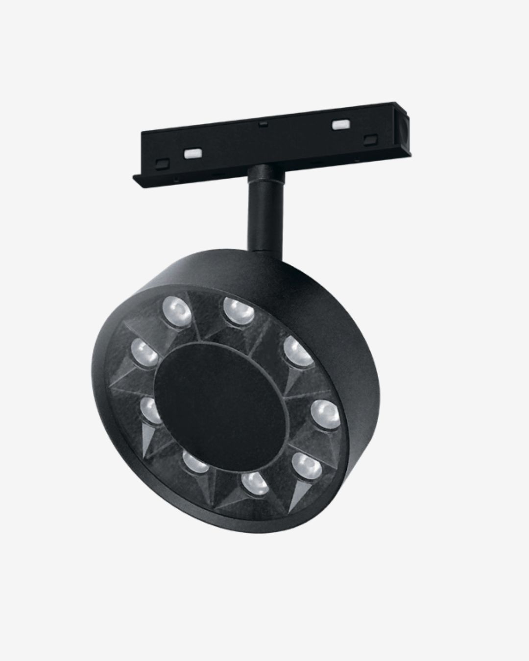
Spot Light — Lens
EN-MGCL · 10W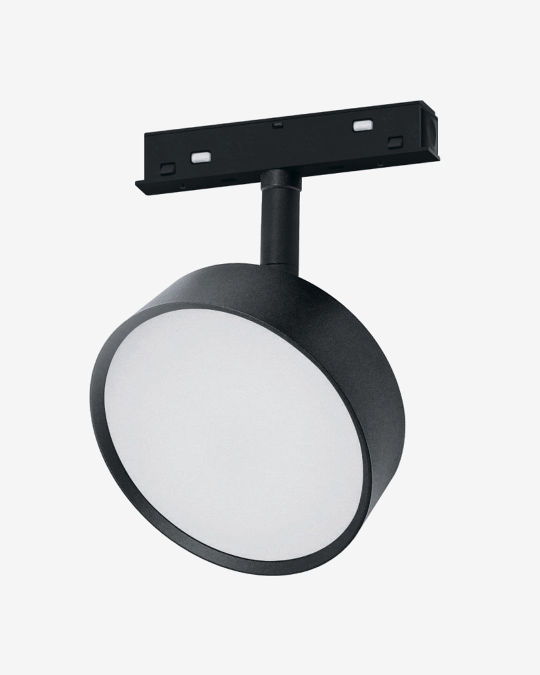
Spot Light — Diffuser
EN-MGCD · 10W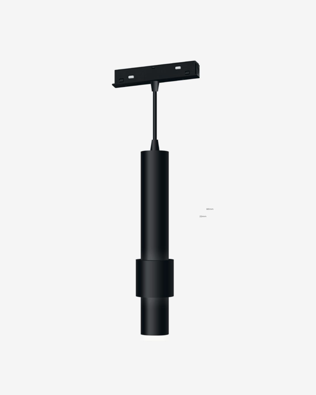
Suspended Pendant
EN-MGCY6 · 8W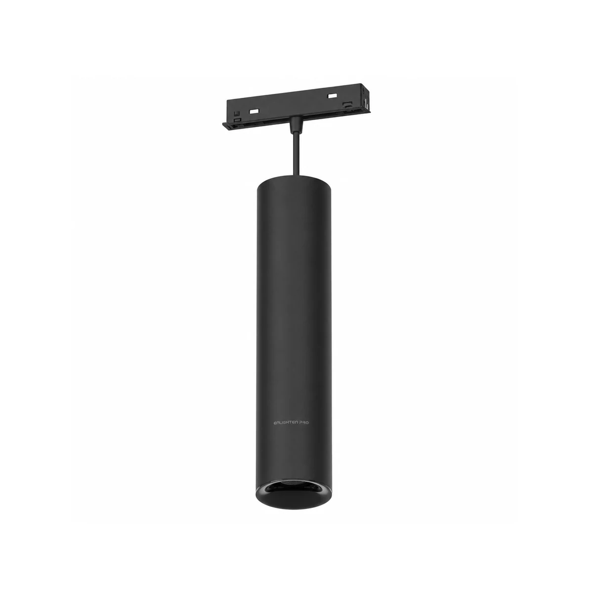
Suspended Pendant
EN-MGCY7 · two sizes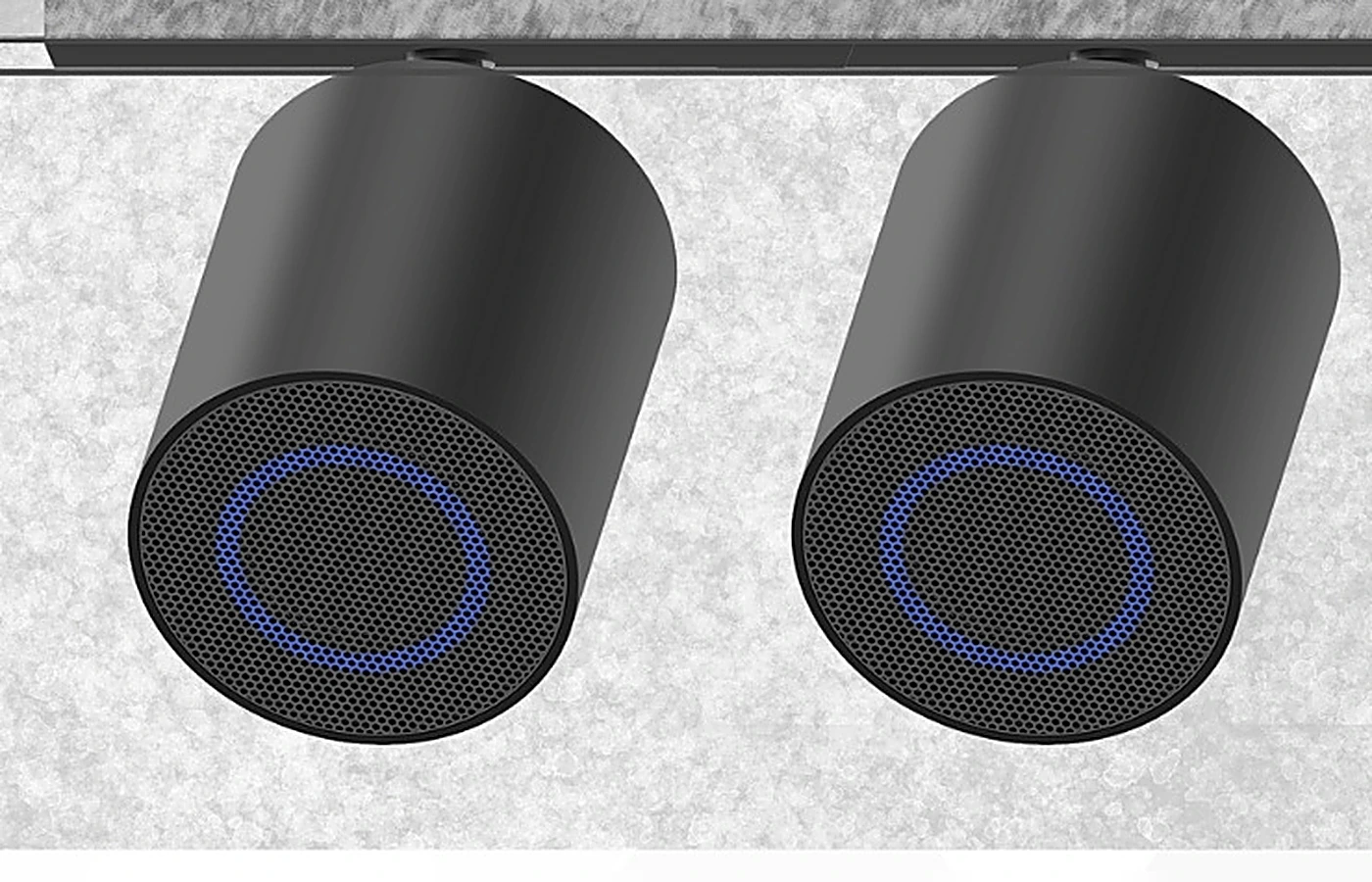
Sonic Beam speaker
EN-SONIC-BEAM · CIANA mount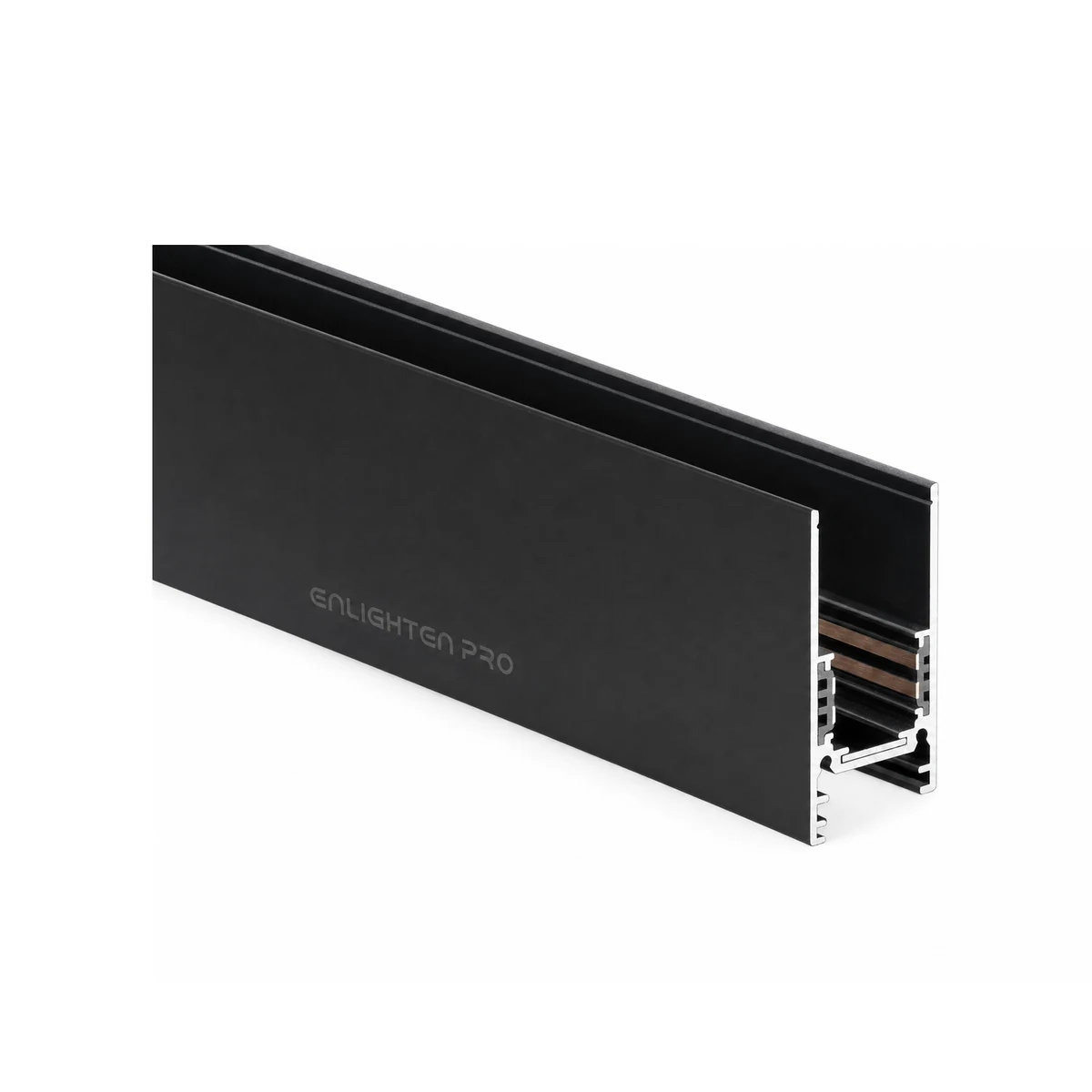
The full range
Every code, on one pageIf something is dark
Four faults cover almost every call. Work from the luminaire back to the supply.
One luminaire does not light
It is not fully home. Take it off and offer it up square: a head that seats properly pulls itself the last few millimetres and lights as it lands.
Everything after a joint is dark
The joint is missing its module, or the module is not pushed fully into both track ends. Every joint needs both: a jointer to hold the lengths in line, and a straight or corner module to take the 48V across.
The far end of a long run is dimmer
Voltage drop. Keep a jointed run to about 5m in one group and feed a longer ceiling as more than one run.
The whole run is dark
Start at the supply. Check the mains side, that the supply or the input module is seated in the end of the track, and that the total luminaire wattage on the run is inside the supply's rating.
Planning a run?
Send the ceiling plan and we will come back with the channel lengths, the connectors, the supply rating and the luminaires, listed in the order they go up.