 CIANA 48V on DALI · Wiring guide
enlighten.biz/ciana-48v-dali
CIANA 48V on DALI · Wiring guide
enlighten.biz/ciana-48v-dali
Wiring guide
CIANA 48V on DALI.
The 48V channel carries four conductors: two for power, two for DALI. This page is how the four get onto the track with either supply, where Enlighten Pro's part of the job ends and the automation contractor's begins, and the rules a DALI line has to keep.
Fixing the track itself? That is the CIANA 48V installation guide. Come back here for the wiring.
What DALI needs from the track
DALI is the digital language a lighting controller uses to speak to each luminaire over one two-wire pair: every luminaire has its own address, and dims, switches or changes colour on command.
Four conductors, two jobs. Read this before the wiring: most DALI call-backs are one of these four things not understood.
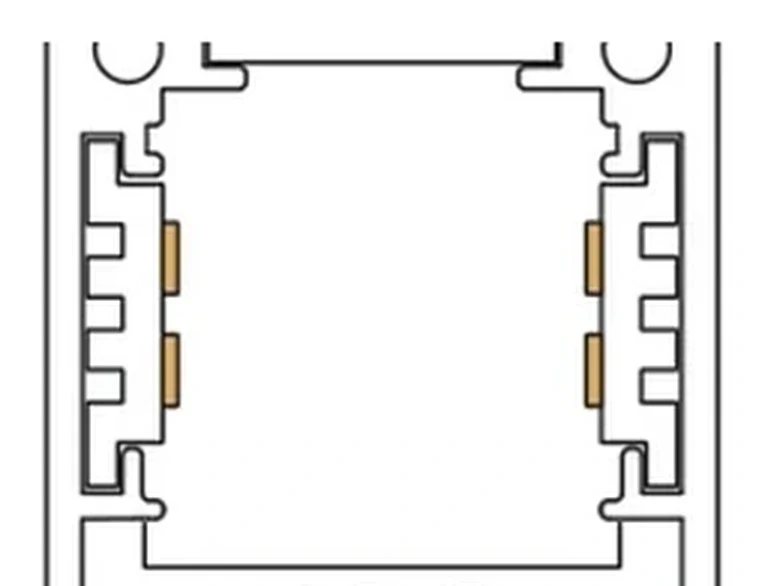
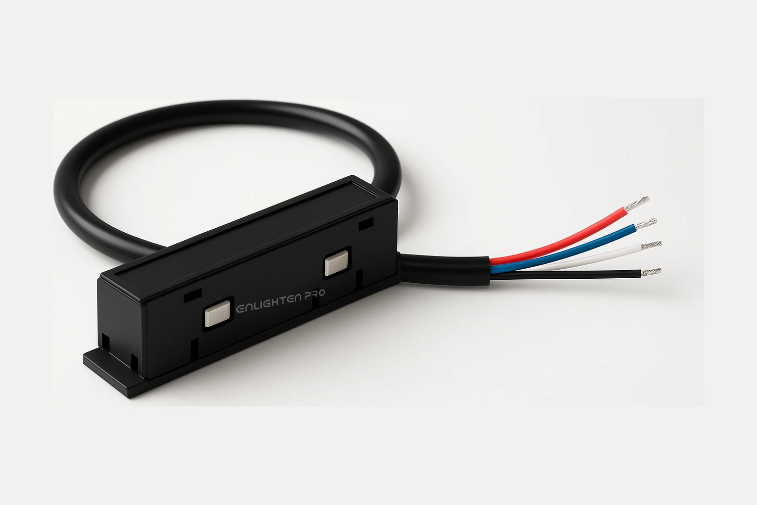
Two conductors carry 48V
The red and blue wires. Every luminaire draws its power from this pair, exactly as on a run without DALI.
Two conductors carry DALI
The black and white wires. A DALI-2 luminaire listens on this pair for its address and its commands. Polarity does not matter — DALI is designed so the two cannot be connected the wrong way round.
The DALI line needs its own supply
DALI runs at 16V and draws up to 250mA. That does not come from the 48V supply. It comes from the DALI controller, or a separate bus supply, on the automation contractor's side — and there must be exactly one on a line. So three things make power on a DALI run: the 48V supply for the track, the 16V bus supply for the line, and the driver in each head that turns 48V into LED current.
All four cross a joint
The straight module and the corner module carry all four conductors from one length to the next, not just the two power ones. DALI reaches the whole run, through every joint and every corner. The jointer is mechanical and carries nothing, as it does on a run without DALI.
One line, several runs
A long ceiling is fed as several runs of about 5m, each with its own 48V supply, exactly as on a CIANA run without DALI. Where two runs meet they are held by the jointer only, which carries nothing — so neither 48V nor DALI crosses, and two supplies are never joined. Each run gets its own input module, and the DALI cable goes from module to module: one line, many runs.
One line, 64 addresses
A DALI line carries at most 64 control gear, addressed 0 to 63. Each DALI-2 luminaire on the track is one of them. Past 64, it is a second line.
This page is the 48V magnetic track. A luminaire with its own mains-fed driver, and LED strip on a constant-voltage driver, land their DALI wires differently: all three are on DALI wiring guides.
Before you start
Eleven rules. Every one of them is a call-back avoided.
- Install to local and national electrical regulations, and only by a licensed electrician who knows how the system goes together.
- Isolate at the distribution board before anything is touched, and prove it dead — and on a DALI line that means every circuit feeding gear on that line, not only the one being worked on. The line also reaches mains-fed equipment — the controller, its bus supply, and whatever else shares the line — and a fault in any of them can put the DALI pair at mains potential.
- The track carries 48V DC on one pair and DALI on the other. Never connect either pair, or the track, to the mains.
- DALI-2 luminaires are made to order with the DT6 or DT8 driver inside. Samples must be tested and approved by the automation contractor before the order is placed.
- One bus supply per DALI line. A second one on the same line conflicts with the first and the line stops working.
- No more than 64 control gear on one line — that is every driver on it, and a head above 24W carries two. Under DALI-2 the sensors and wall panels are control devices and are counted separately, in a 64 of their own. Leave a few addresses spare either way.
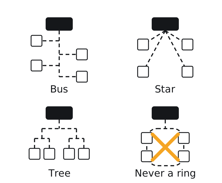
- A DALI line is a bus, a star or a tree. Never bring it back on itself as a ring.
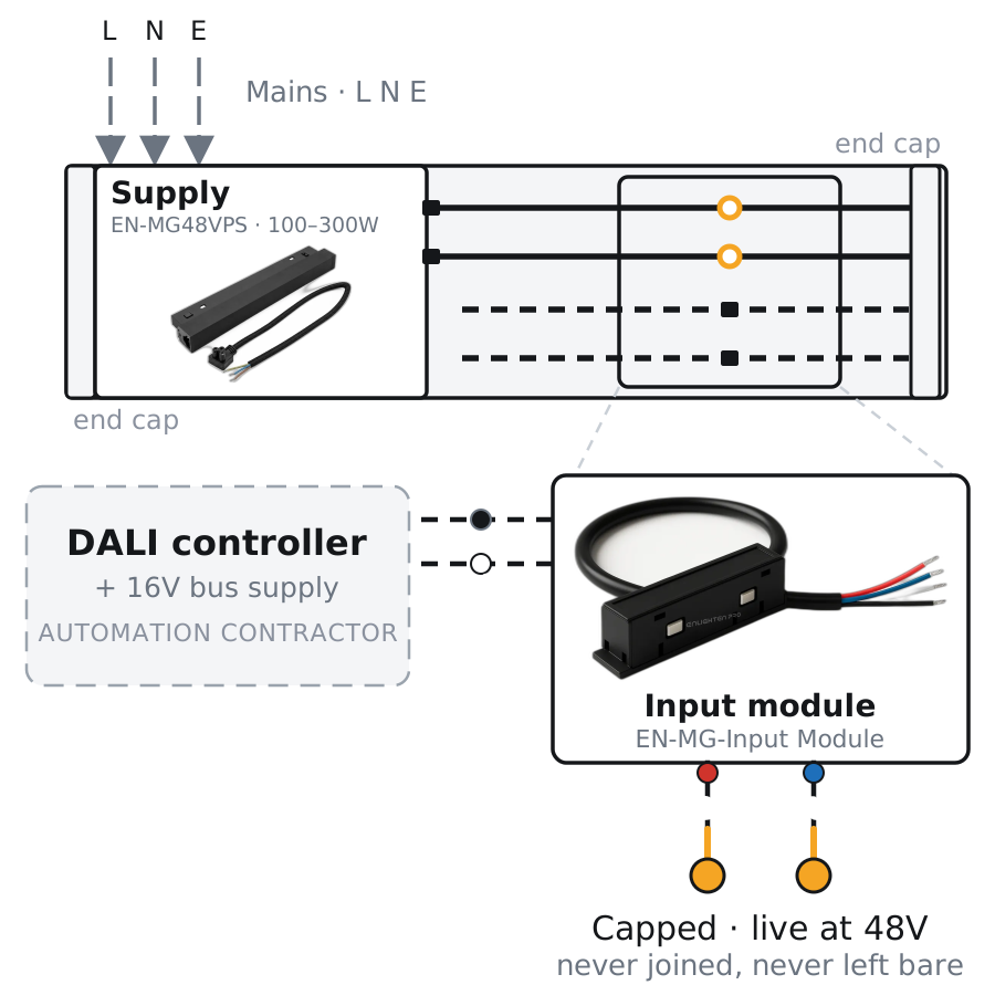
- Where the input module carries DALI only, its red and blue wires are still live at 48V from the conductors they touch. Cap each one separately. Never leave them bare and never join them.
- Bring the DALI line onto a run at one point only. A second input module landed on the same line joins the two DALI conductors back to the controller a second way, and that is a ring.
- Feed the 48V supply from an unswitched circuit. A head with no 48V is off the line: it cannot be addressed, and a scene that reaches it does nothing.
- The 48V supply has three mains leads — line, neutral and earth — and all three are connected. Earthing and bonding are to local regulations, as on any installation.
Who supplies what
Enlighten Pro supplies the track and everything that sits in it. The DALI controller, its bus supply and the DALI cable come from the automation contractor, who also commissions the line.
| Part | Code | What it does |
|---|---|---|
| Track channel | EN-MGTS · EN-MGTR | Four conductors: 48V on one pair, DALI on the other. Enlighten Pro |
| Input module | EN-MG-Input Module | Four wires to four contacts, no electronics, no DALI address of its own. Red and blue for 48V, black and white for DALI. Pushes into the track end or in line — the module as a product. Enlighten Pro |
| 48V supply, external | EN-SMPS04 48V | Sits in the ceiling void and feeds the input module. Order the 48V version — the same code is also sold in 24V, and a 24V unit will not run this track. Method A. Enlighten Pro |
| Integrated supply | EN-MG48VPS | 100, 200 or 300W, sitting in the track end. Method B. Enlighten Pro |
| DALI-2 luminaires | DT6 · DT8 | A CIANA 48V luminaire ordered with the DALI-2 driver inside: DT6 dims, DT8 dims and tunes colour temperature. The 48V driver is rated to 24W. A head up to 24W has one driver and is one address on the line; a head above that is built with two drivers, one per LED board, and is two addresses — grouped together, it behaves as one. Enlighten Pro |
| DALI controller | — | The application controller or gateway that runs the line, with the 16V bus supply built in or beside it. Automation contractor |
| DALI cable | — | Two-core, mains-rated. 0.5mm² to 100m, 1.0mm² to 200m, 1.5mm² to 300m. Automation contractor |
DT6 or DT8
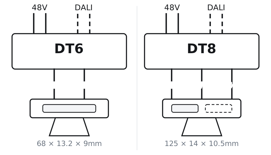
The DALI driver is not in the ceiling. It sits inside each luminaire, behind its magnetic mount, and it is the only part of a CIANA run that differs between a head that dims and a head that also tunes colour. Everything on the track is the same either way.
There is no second wiring diagram
A DT8 run is wired exactly like a DT6 run. Same track, same four conductors, same input module, same supply, same two-core DALI cable. Nothing in Method A or Method B changes because a head tunes colour.
One address either way
Each driver is one DALI device with one short address, DT6 or DT8; a head up to 24W has one driver, a head above that has two and is two addresses. On a DT8 the same address carries the colour temperature as well as the level — which is why a tunable head does not cost a second address, and why 64 still means 64.
What actually differs
The DT6 driver has two output leads, LED+ and LED−. The DT8 has three: a common LED+ with a warm return and a cool return. It is longer too — 125mm against 68mm.
The controller has to speak DT8 too
A DT8 head on a controller that only handles DT6 will dim perfectly and never change colour temperature. Check the controller's device-type support before the order. Its warm and cool limits are set at commissioning, not fixed in the driver.
It is chosen when the light is ordered
The driver is fitted inside the luminaire, so DT6 or DT8 is decided on the order, not on site. Samples are tested and approved by the automation contractor before the order is placed.
Both are DALI-2 drivers running on 48V and switching above 3600Hz; each draws under 2mA from the DALI line. Over DALI the standard dimming curve's lowest step is 0.1% of full output. The 48V driver is rated to 24W; a head above that carries two, one per LED board. Under smart controls it is the 6–24W band — the other DALI bands listed there are mains-input drivers for other ranges.
Each driver is a product in its own right, with its full specification: EN-DRV-DT6 and EN-DRV-DT8.
 Alliance

Safri Solutions Pvt. Ltd. is a Community member of the DALI Alliance. The DT6 and DT8 drivers in these luminaires are DALI-2 certified products from an Alliance member.
Method A
External supply and input module
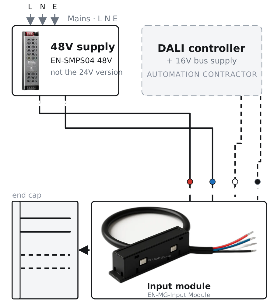
The cleanest route. A supply in the ceiling void makes the 48V, the controller makes the DALI, and the input module puts all four onto the track at once.
Mount the supply in the void
EN-SMPS04 in its 48V version — the same code is sold in 24V too, and a 24V unit will not run this track — or an isolated 48V DC constant-voltage supply such as a Meanwell, loaded to about 80% of its rating as on any CIANA run. Mains — line, neutral and earth — goes to its input through a junction box.
Land the four wires
Red and blue to the supply's V+ and V−. Black and white to the DALI line from the controller — either way round; DALI has no polarity.
Push the module into the track
It goes into the end of the run like the integrated supply would. All four contacts are now live: 48V on the power pair, DALI on the data pair.
Close the far end
End cap on the other end of the run, as on any CIANA 48V install.
Method B
Integrated supply and input module
Where the run uses the supply that sits in the track. The supply makes the 48V; the input module is still needed, but for the DALI pair only.
Fit the supply in the track end
EN-MG48VPS, exactly as in the installation guide. Its lead carries three wires: land live and neutral, and connect the third as the label on the supply states.
Insert an input module in line
Anywhere along the run. Connect only its black and white wires, to the DALI line from the controller.
Cap the red and blue
The module's power contacts are touching the live power conductors, so those two wires carry 48V. Insulate each one on its own. Never join them, never leave them bare.
Nothing else
Power from the supply, DALI from the module. The run is wired.
The DALI line
The track is one stretch of a DALI line that the automation contractor owns. These are the limits that line has to keep, wherever it runs.
Voltage and current
16V DC on the bus, 250mA maximum from the bus supply. Every device on the line draws a share of it.
Cable
Two-core, and rated for the mains voltage of the installation. DALI is not a safety extra-low-voltage circuit: inside control gear it is separated from the mains by basic insulation only, so the pair is wired and handled as mains-voltage wiring — and that is the basis on which local wiring rules may allow it to share containment with mains; the call is theirs. Size it by the drop: 0.5mm² up to 100m of line, 1.0mm² to 200m, 1.5mm² to 300m. Those figures come from one rule — the drop along the pair must stay under 2V, and no line may exceed 300m.
Polarity
None. The two DALI conductors can be connected either way round at every luminaire, by design.
The controller must address
A broadcast-only DALI output — found on some KNX gateways and some Lutron and Crestron interfaces — sends one level to everything and cannot address, so there are no groups, no scenes and no identify. The line needs a DALI application controller that assigns addresses. A DALI version-1 controller does that for these drivers too; DALI-2 is not required of the head end.
No emergency gear here
There is no emergency-lighting (DT1) gear in this range. Emergency luminaires are the contractor's own line and their own address budget.
One supply, 64 devices
Exactly one bus supply on a line, and at most 64 control gear on it. A second supply, or a sixty-fifth device, is a second line.
Commissioning
The automation contractor's job, once the track is wired and powered. Four steps: three at the controller, and one on foot.
Address
The controller scans the line and gives every DALI-2 luminaire a short address — its number on the line — from 0 to 63. A luminaire that is not seated on the track will not be found.
Identify
Addresses land in the order the controller finds the luminaires, which has nothing to do with the order they sit in on the run. The commissioner blinks one address at a time and walks the job, writing down which head it is. On a full line this is most of the commissioning time, and the schedule it produces is what makes the system maintainable afterwards.
Group
Addresses are sorted into up to 16 groups that match the rooms or zones — a group is what a switch or a sensor speaks to. One luminaire can sit in several groups at once, which is how a light belongs to both a room and a scene-wide zone.
Scene
Up to 16 preset levels are stored and recalled with one command. On DT8 luminaires a scene carries colour temperature as well as level.
Groups and scenes are software. A zone can be changed without touching a wire — which is the reason to specify DALI in the first place.
If something does not respond
Four faults cover almost every call. Decide first whether it is the power side or the DALI side.
They light, but do not dim
The DALI pair is not reaching the track. Check black and white are landed and the module is pushed fully home, then check the line has a bus supply at all. A driver that hears nothing falls back to its system failure level, which is full output as it leaves the factory — so full brightness with no response is the signature of no DALI, not of a broken head. If only the heads past a joint are affected, the straight or corner module at that joint is not seated: it carries all four conductors, and a module that is half home carries none of them.
One luminaire does not respond
It is not fully seated, or it has not been addressed. Take it off, offer it up square until it lights, then have the controller scan again.
Nothing on the line responds
A short across the DALI pair, or no bus supply on the line at all. Either stalls the whole line, and the signature is every head sitting at full output and ignoring the controller. Then check there is exactly one bus supply on the line — a second one is the next thing to look for.
A head was replaced and its zone is broken
A new driver arrives unaddressed. It inherits nothing from the one it replaced — not the short address, not the groups, not the scene levels, not the colour limits. Most DALI-2 application controllers have a replace-device routine that hands the freed address to the new gear and pushes its settings back. Swapping a head is a fitting job; putting it back on the line is a commissioning one.
Nothing lights
That is the 48V side, not DALI. Work through the checks on the installation guide.
Planning a DALI run?
Send the ceiling plan and the controller you are working with, and we will come back with the luminaire list with the right drivers, the supply, and the modules, listed in the order they go up.