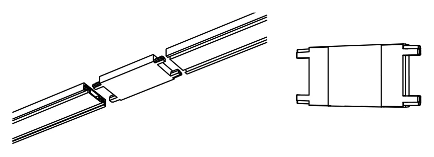
Straight joint
Two lengths in line. The jointer pushes into the end of each length and the run continues as one.
EN-CE-Jointer Module
 CIANA Elance' 6mm · Installation guide
enlighten.biz/ciana-elance-6mm-install
CIANA Elance' 6mm · Installation guide
enlighten.biz/ciana-elance-6mm-install
Specifications subject to change · [email protected]
| ||||||||||||||||||||||||||||||||||||
|
Installation guide CIANA Elance' 6mm, installed.The 26 × 6mm magnetic track, from a bare ceiling to a lit luminaire, in four stages. Written for the electrician on site: print it and take it up the ladder. Fitting the deeper CIANA 48V track instead? That system goes together differently and has its own guide. Watch it go togetherEighty seconds, no commentary: the channel goes up, the connectors go in, the luminaires push on. Worth watching once before the first run. The film has music but no commentary — nothing is missed with the sound off. Before you startEleven rules. Every one of them is a call-back avoided.
The partsEverything a run is built from, in the order it goes up. Codes are the price-list codes.
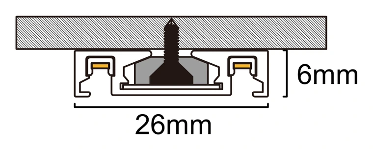
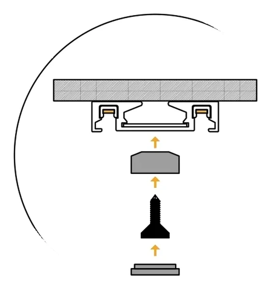
Stage 1 of 4 Fix the trackThe track is screwed to the ceiling through its own centre channel, three fixings to the metre, and every screw head disappears under a cover. 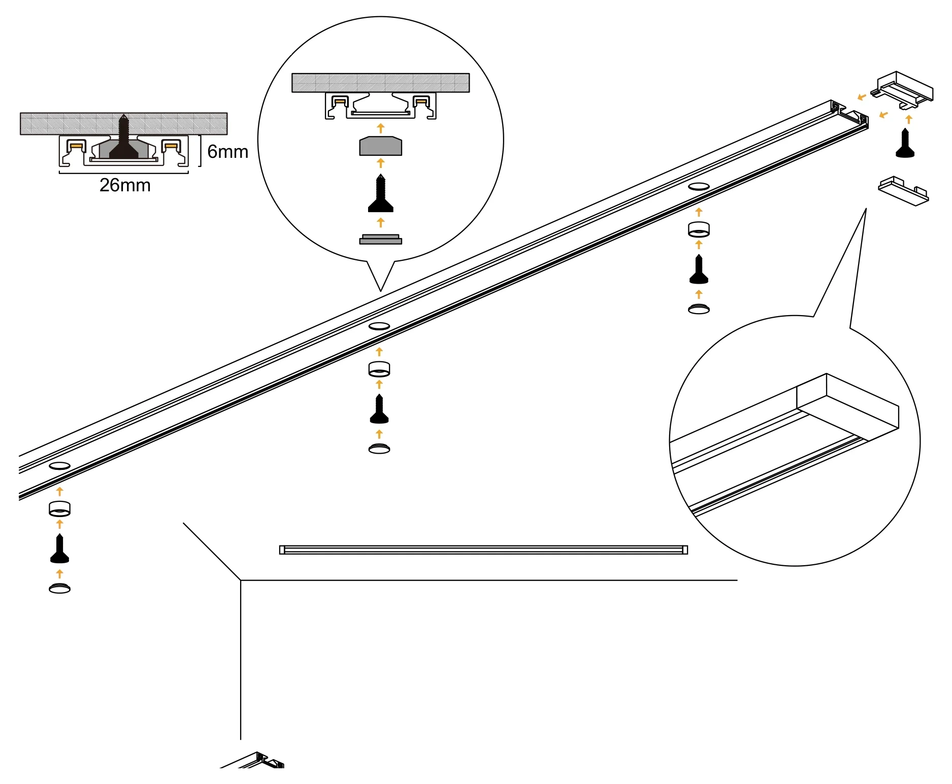
01
Check the fittingsFor each length: the track itself, plus positioning plugs, screws and screw-hole covers from the mounting kit. Three of each per metre. 02
Set out the runMark the ceiling from the lighting layout. Offer the track up on the line, push a positioning plug into the first fixing hole, drive the screw, then press the cover over the screw head. 03
Screw every holeThe channel has three fixing holes in every metre. Fix all of them: the track is only secure once the whole length is drawn tight to the ceiling. 04
Close the endAt the open end of the run, fit the end plug, screw it and cover the screw. The track is ready for its joints and its power. Stage 2 of 4 Join the lengthsEvery joint is mechanical and electrical at once: the connector pushes into both lengths and carries the 48V across. Five joints cover any layout.
Straight jointTwo lengths in line. The jointer pushes into the end of each length and the run continues as one. EN-CE-Jointer Module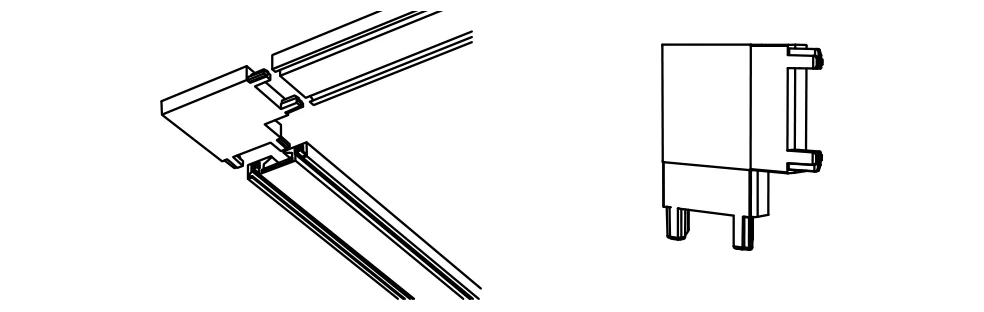
Corner jointA 90° turn in the plane of the ceiling, powered through the corner. The listed part is the curved version; the square corner drawn here is available on the enquiry. EN-CE-Curved Corner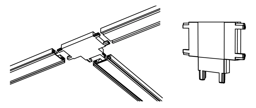
Tee jointA branch off a straight run. The tee carries power into all three legs. EN-CE-Tee Connector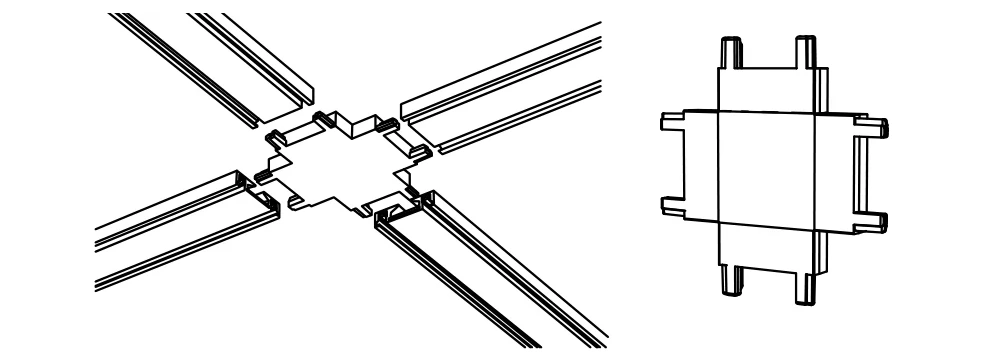
Cross jointFour legs from one point, for a grid across a ceiling. EN-CE-Cross Connector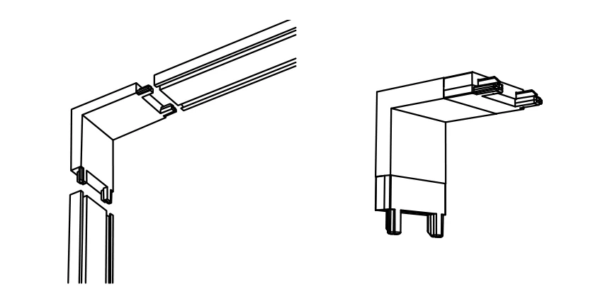
Vertical cornerA ceiling run turning down onto a wall run, powered through the corner. EN-CE-Vertical Corner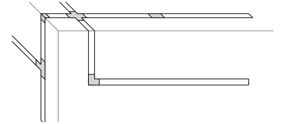
Ceiling to wallWhere the vertical corner goes: the run leaves the ceiling line and continues down the wall as the same circuit. LayoutEvery connector is fitted the same way: push it fully into one length, then push the next length onto it. Send us the layout and we will list the connectors the run needs. Stage 3 of 4 Bring in powerMains never reaches the track. It is converted to 48V first, either by a supply that sits in the track or by one above the ceiling feeding an input module. Check the input range on the supply's own label before you connect it. 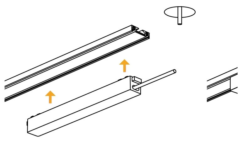 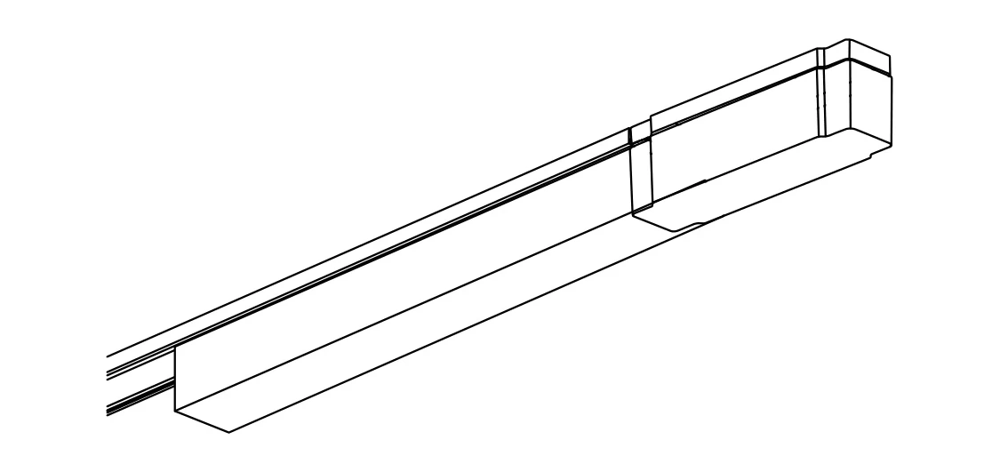 Option A Supply in the trackThe EN-CE48VPS supply is built to sit in the track channel. Bring the mains lead — three cores, line, neutral and earth — through the ceiling, join all three in a junction box above the ceiling, then push the supply up into the track exactly as you would a luminaire. It puts 48V onto the copper strips from where it sits. The wire box hides the lead where it enters the track. Listed at 100W and 200W. Add up every luminaire on the run and choose the rating above that figure.  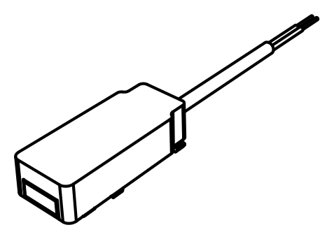 Option B Supply above the ceilingMount a 48V supply in the ceiling void and run its output down to the EN-CE-Input Module, which clips into the end of the track. From there the copper strips carry 48V to every luminaire on the run. The listed match is the EN-SMPS04 48V driver. Size it the same way: total luminaire wattage, then the rating above it. One supply feeds one run. A run that is joined through corners and jointers is still one run; a second, separate track is a second supply. Stage 4 of 4 Mount the luminairesNo tools. Push, press, done. The luminaire lights the moment its contacts meet the copper strips, so you know it is seated before you lock it. 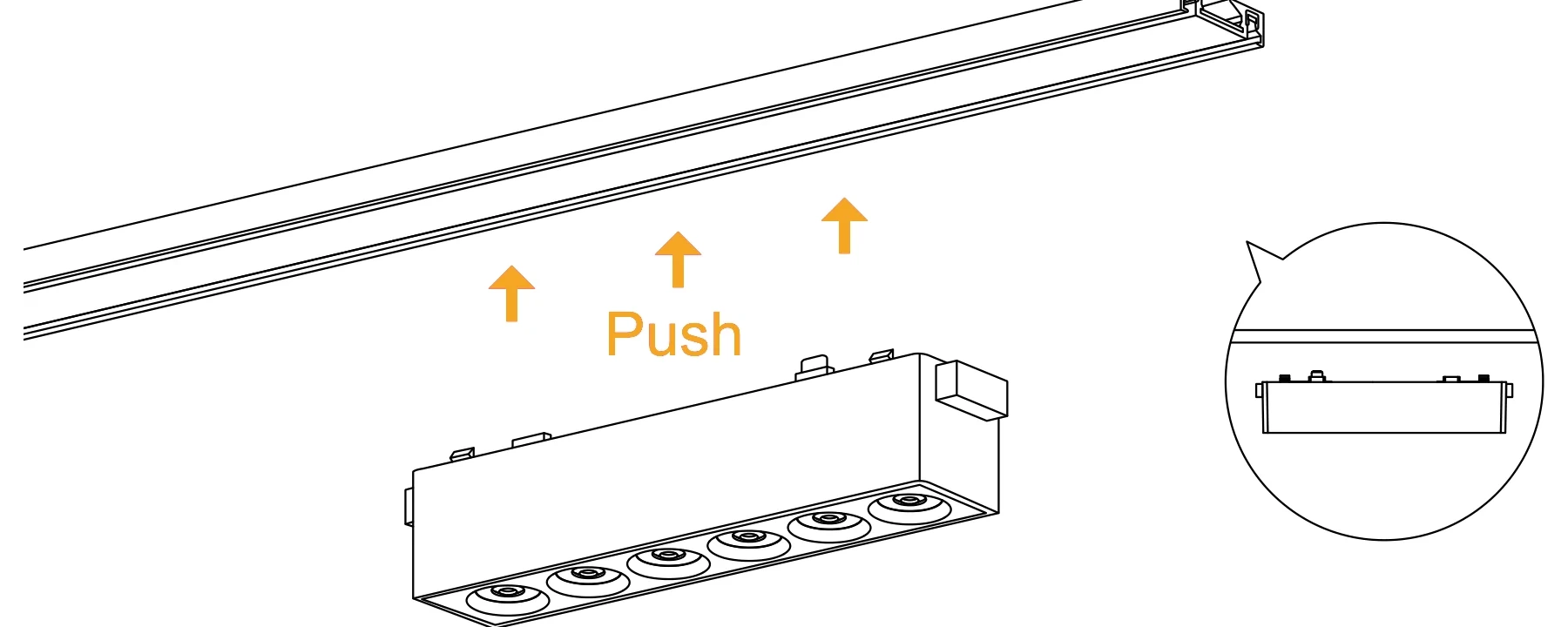 01 PushOffer the luminaire up to the track and push it home so the copper contacts on its back meet the copper strips in the channel. It lights as soon as they touch. 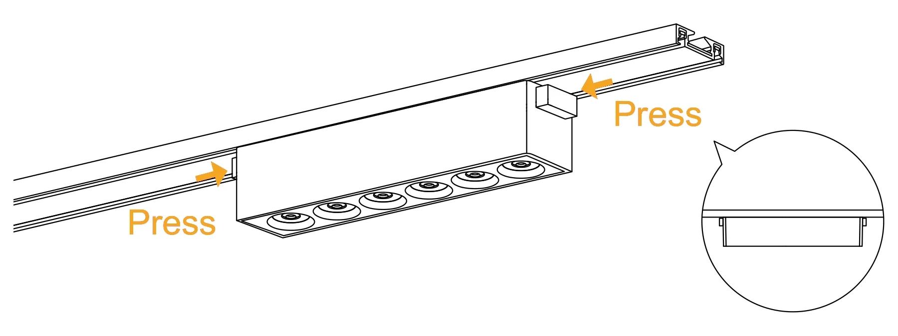 02 PressWith the luminaire lit, press the catch at each end inwards. They lock the body to the track so it cannot be knocked out or slide. 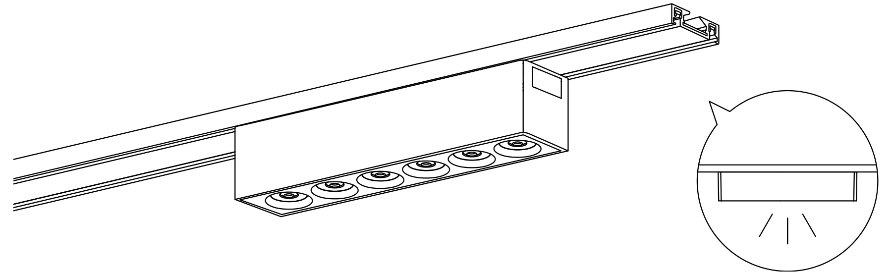 03 SeatedFlush in the channel, locked and lit. To reposition it, release both catches, slide, and lock again. Every luminaire in the Elance' range mounts the same way.  Spot LightEN-CETL · 7 / 12 / 18W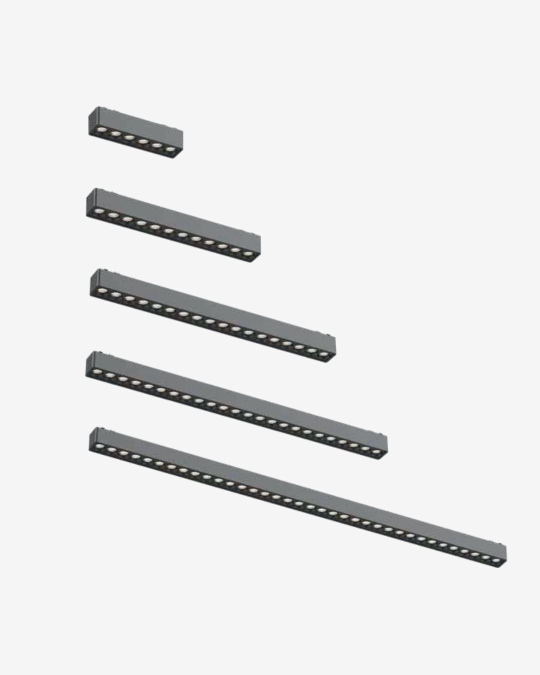 Laser LightEN-CELL · 6 / 12 / 18W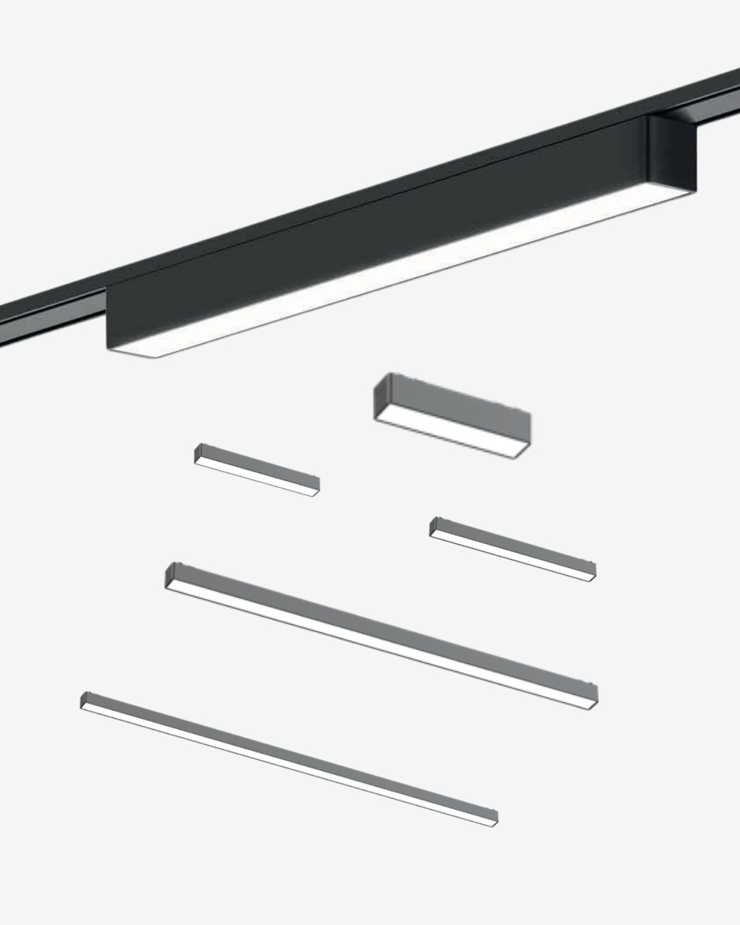 Linear LightEN-CELN · 10 / 20 / 30W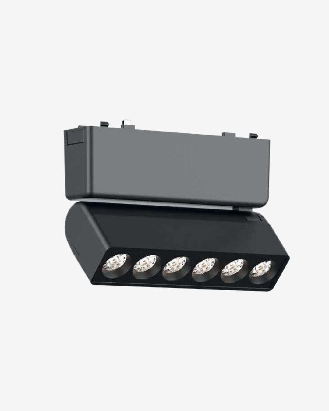 Rotatable Laser Blade SpotlightEN-CELLR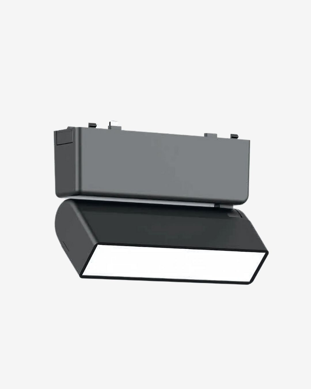 Rotatable Laser Blade Flood LightEN-CELLRD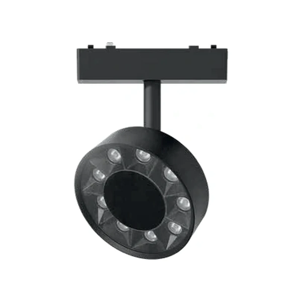 Spot CLEN-CECL · 10W · lens optics Spot CDEN-CECD · 10W · diffuser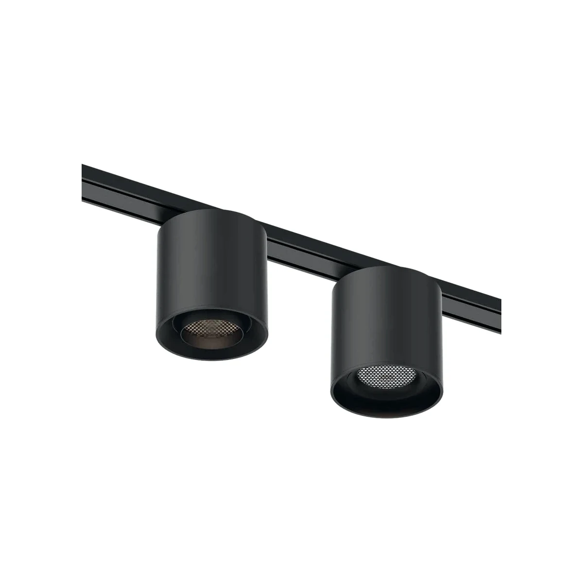 Cylinder PendantEN-CECY1 · 12W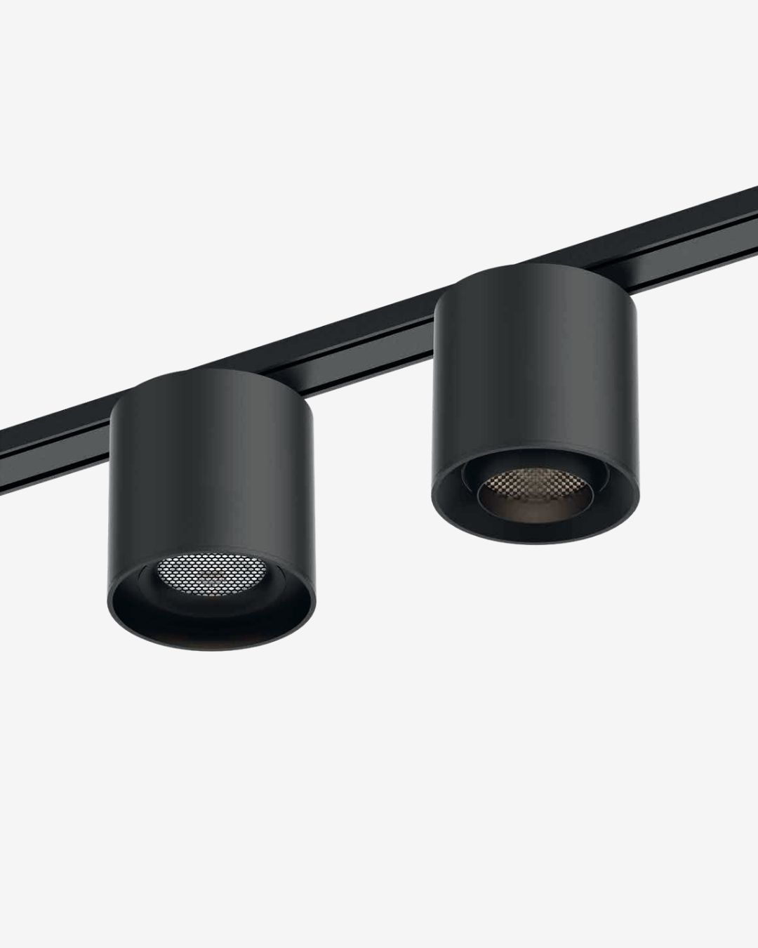 Cylinder Spotlight with HoneycombEN-CECY-01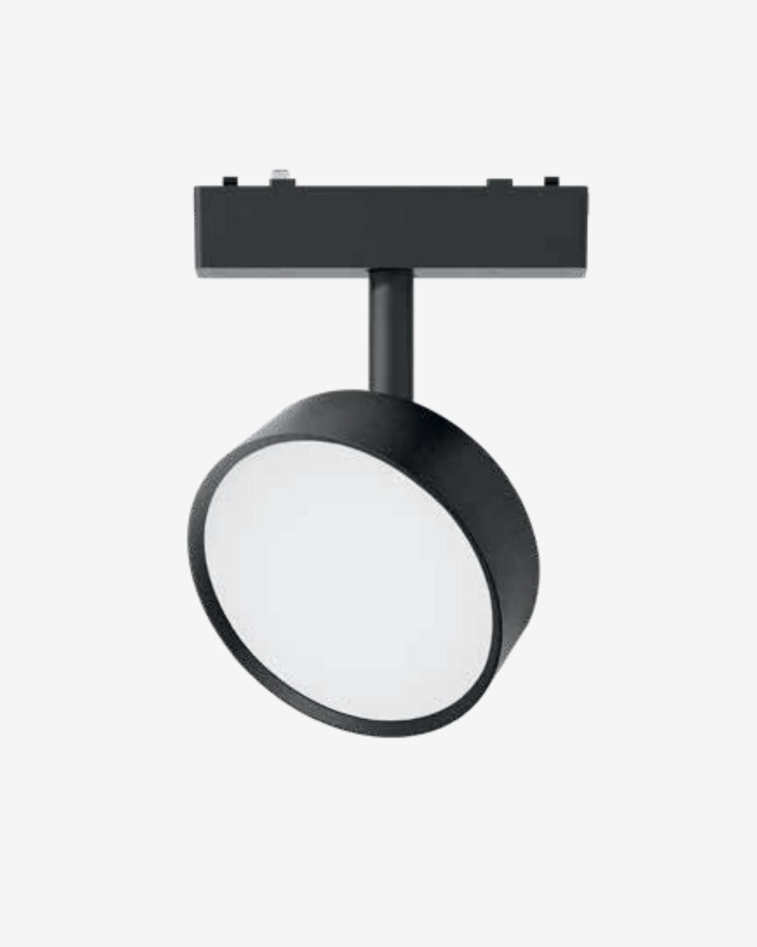 Round Movable Wall WasherEN-CE-RWW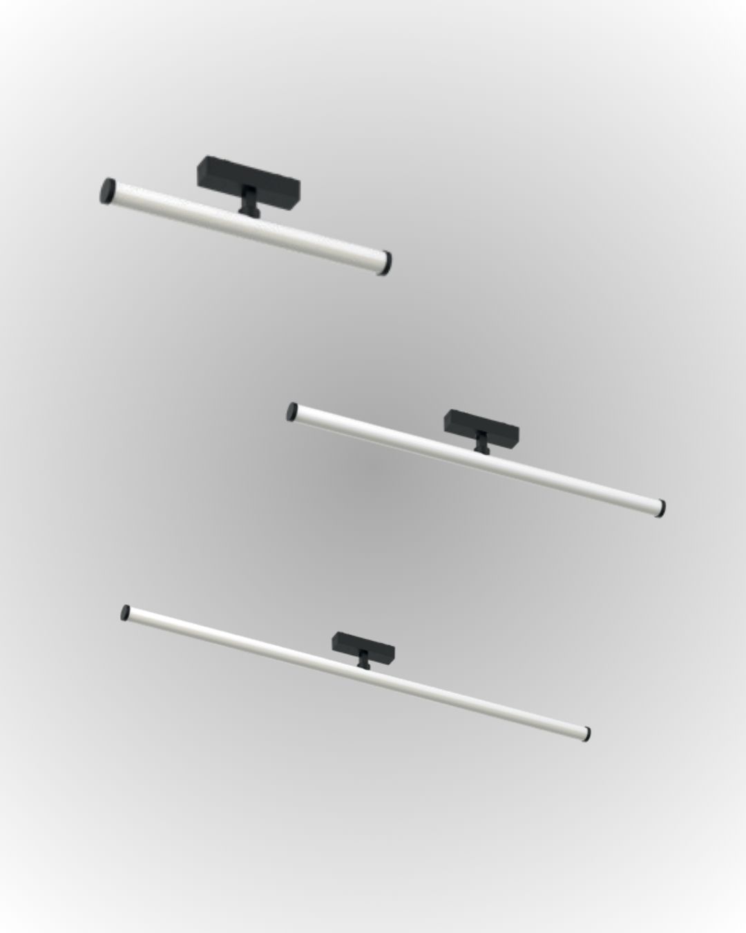 360° Glowing Linear TubeEN-CETB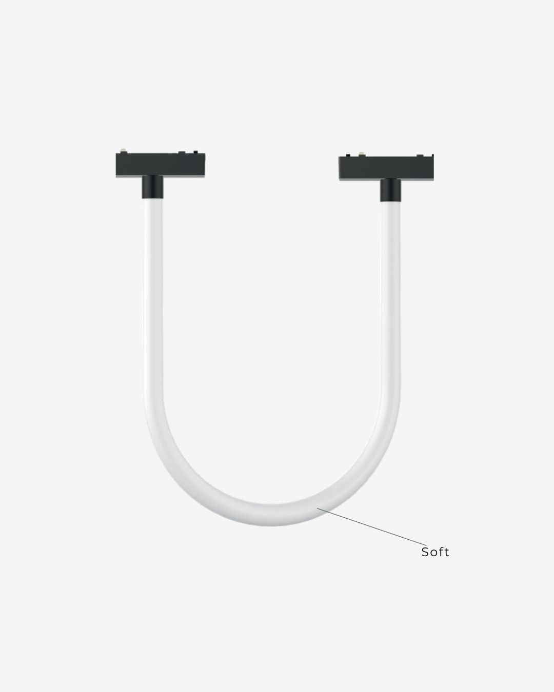 360° Glowing Flexible NeoFlexEN-CENF Pendant GlobeEN-CECP-01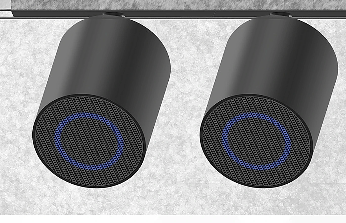 Sonic Beam speakerEN-SONIC-BEAM · Elance' mount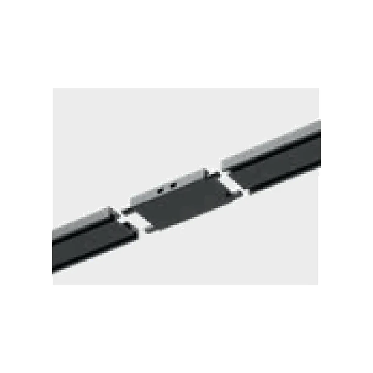 The full rangeEvery code, on one pageIf something is darkThree checks, in the order they usually turn out to be the answer. One luminaire does not lightIt is not pushed fully home. Release the catches, take it off, and push it up again until it lights; only then press the catches in. Everything after a joint is darkThe jointer or corner is not seated in both lengths. Check that the connector has pushed fully into each track end; the joint is what carries the 48V across. The whole run is darkStart at the supply. Check the mains side at the junction box, that the supply or input module is seated in the track, and that the total luminaire wattage on the run is within the supply's rating. Still dark? Send us a photo of the run and the supply and we will work it through with you on WhatsApp. Planning a run?Send the ceiling plan and we will come back with the track lengths, the connectors, the supply rating and the luminaires, listed in the order they go up. |