 Meridian tensioned line · Installation guide
enlighten.biz/meridian-install
Meridian tensioned line · Installation guide
enlighten.biz/meridian-install
Installation guide
Installing Meridian
Meridian is a 13mm steel belt drawn tight between two brackets, with a 24V COB strip stuck along its face. Nothing holds the span in the middle — the two brackets carry all the tension — so where they go, and what they are fixed into, decides the job. The order is: plan the line and the power, fix the brackets, string and tension the belt, then stick on the strip, connect it and aim it.
The parts
| Part | Code | Notes |
|---|---|---|
| Bracket set | EN-MRD-ACC | Sold as a pair, one for each end. Each bracket is a round base, a universal rod (threaded, with a ball joint) and a connecting rod with a hex socket screw. Spins 360°, tilts 62°. |
| Steel belt | EN-MRD-BELT | 13mm wide, sold per metre, cut to the span on site. Spans 1–20m. |
| COB strip | EN-MRD-COB24 | 24V DC, 10W/m, 3000K or 4000K, CRI 80+, up to 10mm wide. Sold per metre. |
| Power supply | Not included | A 24V constant-voltage power supply (SMPS), bought separately — see the Treiber range under Power Supplies. |
You will need: a drill, wall plugs and screws for four holes per bracket, a screwdriver, a hex key, a measuring tape and a multimeter.
Mains wiring to the power supply is a job for a licensed electrician. Switch off at the breaker first. Meridian itself runs on 24V DC.
Stage 1 of 4
Plan the line and the power
-
A
Choose the route.
Wall to wall across the room, wall to ceiling on the diagonal, or close to and along a wall. The line can run level, sloped, or vertical.
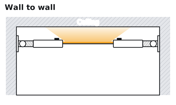
Wall to wall, across the room. 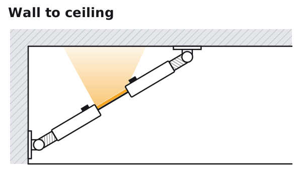
Wall to ceiling, on the diagonal. 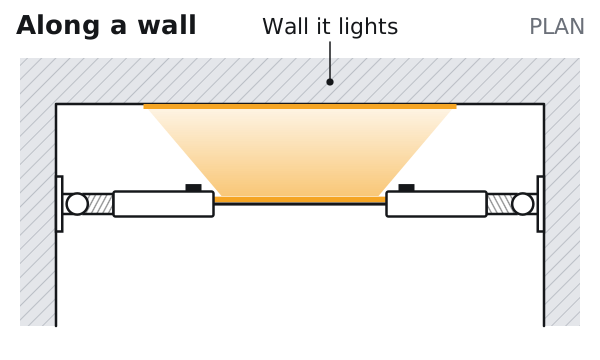
Along a wall, close to it. -
B
Keep at least 31° between the belt and each surface a bracket is fixed to.
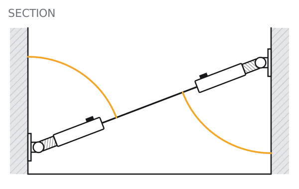
Wall to wall, sloped: at least 31° at each bracket. 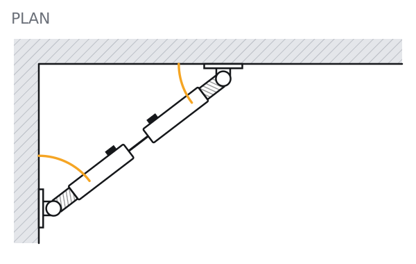
Corner to corner, in plan: at least 31° at each bracket. -
C
Fix only into masonry, concrete or a timber stud.
The belt is under real tension and both brackets carry it. Plasterboard alone will not hold — find solid material behind it, or block it out before the ceiling or wall is closed.
-
D
Decide where the power supply sits.
Either way the 24V DC lead enters through the bracket, so nothing hangs in the span. Use #16AWG cable (about 1.3mm²) from the power supply to the bracket, and keep that run short.
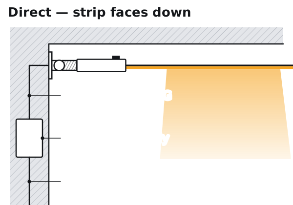
Direct light: the strip faces down; the power supply sits in the wall below the bracket. 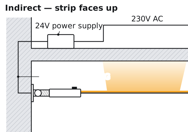
Indirect light: the strip faces up to wash the ceiling; the power supply sits in the ceiling void. -
E
Feed both brackets on runs over 10m.
Fed from one end, a long run dims towards the far end. Up to 10m, one bracket can feed it. Over 10m, bring the 24V DC lead to both brackets — + to + and − to − at each end.
-
F
Size the power supply.
The strip draws 10W per metre. Load the power supply to 80% or less: add up the watts and divide by 0.8, then choose the next size up.
Run Strip load Divide by 0.8 Choose 5m 50W 63W 100W 10m 100W 125W 150W 15m 150W 188W 200W 20m 200W 250W 300W
Stage 2 of 4 · Steps 1–3
Fix the brackets
-
1
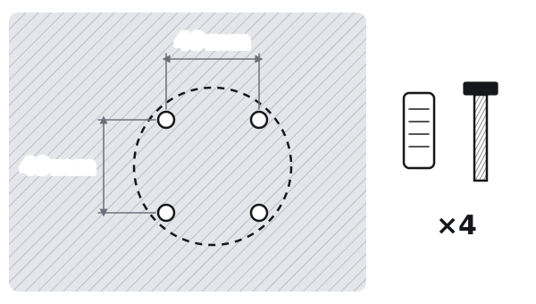
Mark and drill four holes on a 49 × 49mm square, and fit the wall plugs.
-
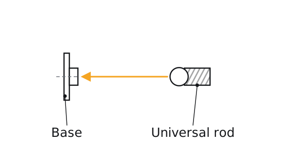
2
Pass the universal rod through the base.
-
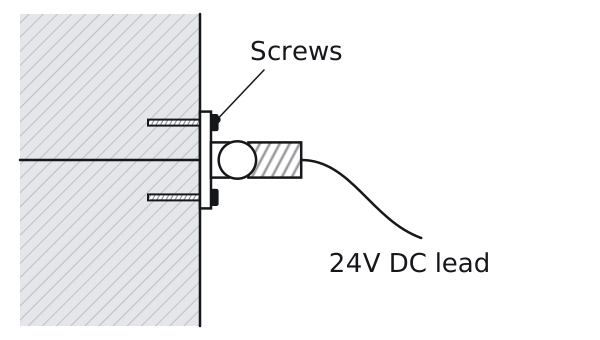
3
Bring the 24V DC lead out through the base and screw the base to the wall.
Repeat at the other end.
Stage 3 of 4 · Steps 4–5
String and tension the belt
-
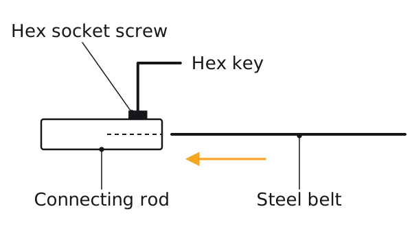
4
Cut the belt to the span. Push one end into a connecting rod and lock it with the hex socket screw.
Do the same at the other end.
-
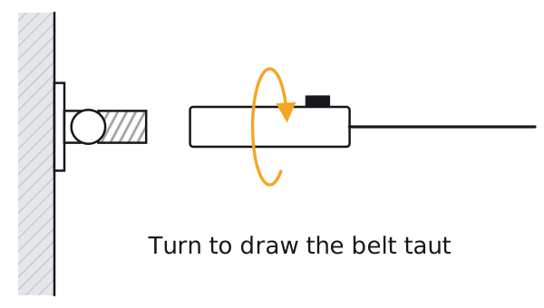
5
Screw each connecting rod onto its universal rod, and keep turning to draw the belt straight and taut.
Stage 4 of 4 · Steps 6–7
Strip, power, aim
-
6
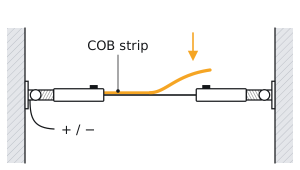
Stick the COB strip along the belt and connect the power.
Unroll the strip before it is ever switched on. Wipe the belt face clean and dry, then peel and press the strip on a little at a time — never stretch it. Connect + to + and − to −.
-
7
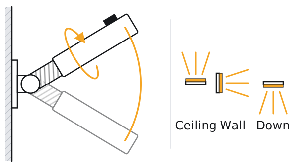
Turn and tilt the brackets to aim the line.
Each bracket spins 360° and tilts 62°, so the strip can face the ceiling to wash it, face a wall to graze it, or face down for direct light.
Before you hand over
The whole length lights, at the same brightness end to end.
The belt runs straight, with no sag.
Both bases are tight to the wall.
No 24V DC lead is visible in the span.
Meridian — parts and prices · Strip lights in profiles — installation guide