 Strip lights in profiles · Installation guide
enlighten.biz/strip-lights-install
Strip lights in profiles · Installation guide
enlighten.biz/strip-lights-install
Installation guide
Strip lights in profiles, installed.
12V and 24V LED strip, cut to length, stuck into an aluminium profile and powered from an SMPS. Fifteen steps in four stages.
Four stages, fifteen steps
- 1
Plan
Before the ceiling is finished.
Steps 1–4 - 2
Prepare the strip
On the floor, before it goes up.
Steps 5–8 - 3
Fix it in the profile
Up the ladder, once the ceiling is painted.
Steps 9–12 - 4
Connect and switch on
Test it before you close the profile.
Steps 13–15
Three rules, before anything else
- Never on 230V. A strip runs on 12V or 24V from an SMPS. Connected to the mains, it burns out at once.
- Never lit on the reel. The coils trap the heat and can unsolder the LEDs. Unroll it first.
- Mains off first. Switch off the MCB and prove the wires dead before you touch the mains side.
Install to local and national electrical regulations, by a licensed electrician.
Stage 1 of 4 · Steps 1–4
Plan
Before the ceiling is finished. Settle it with the ceiling contractor.
-
1
Measure every run. Keep a 12V run to 5m and a 24V run to 10m.
A longer run is split into sections, each with its own feed. For long runs choose 24V: it carries the same light on half the current, so less is lost along the strip.
-
2
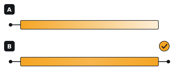
Bring power to both ends of every run.
Fed from one end, a long run dims towards the far end (A). Fed from both ends, the dip falls in the middle, where it shows least (B). We feed both ends as standard.
-
3
Pick an SMPS the strip loads to 80% or less.
Add up the watts of every strip on it and divide by 0.8: 60W of strip needs at least a 75W SMPS. Put it where it can be reached later, with air around it.
CarefulMatch the voltage. A 12V strip on a 24V SMPS burns out; a 24V strip on a 12V SMPS stays dark.
-
4
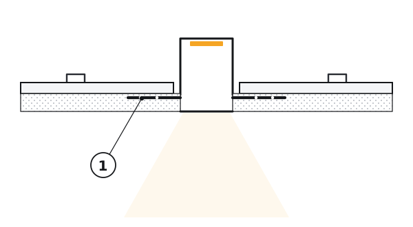
Set plaster-in profiles now, before the POP finish.
Fix the profile through its wings to the board and run its wires. The POP then covers the wings ① and finishes flush with the diffuser. Surface profiles wait until the ceiling is painted.
Stage 2 of 4 · Steps 5–8
Prepare the strip
On the floor or a table, before it goes up the ladder.
-
5
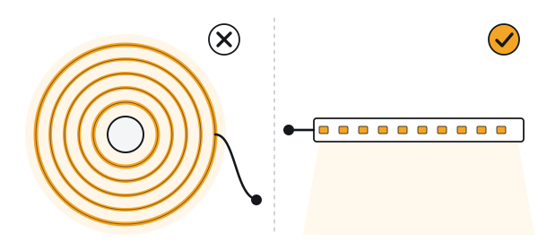
Unroll the strip before it is ever switched on.
On the reel the coils trap the heat, and a strip left lit there can unsolder its own LEDs. Lay it out flat first.
-
6
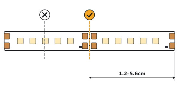
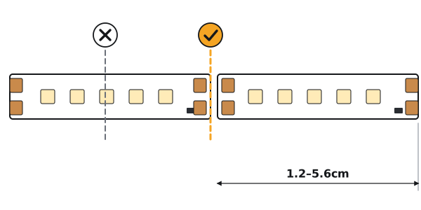
Cut only on the cut marks.
The marks run across the copper pads, every 1.2 to 5.6cm depending on the strip. Cut anywhere else and the section beside the cut stays dark. Each code's cut length is on the LightStream page.
-
7
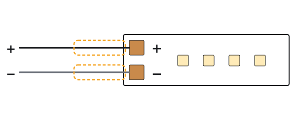
Solder the leads: + to +, − to −.
The pads are marked. Slide a sleeve over each joint so the two can never touch. Our strips are joined by soldering, not with clip-on connectors.
CarefulMark the + lead now, while you can still see the pads.
-
8
Try every piece before it goes up.
Connect it to the SMPS for a moment, flat on the floor, and check every section lights. A bad joint is a minute's work here, and a ladder job later.
Stage 3 of 4 · Steps 9–12
Fix it in the profile
Up the ladder, once the ceiling or wall is finished and painted.
-
9
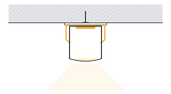
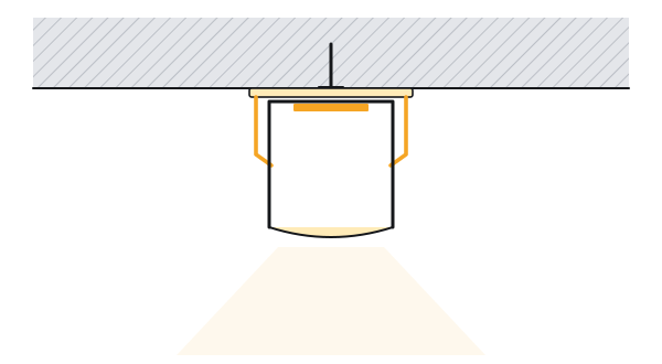
Fix the profile, dead straight.
A surface profile is screwed on, or snapped into clips screwed to the surface — it depends on the profile. A plaster-in profile is already in. The light will show every kink in the line.
-
10
Wipe the channel clean and dry.
POP dust, paint and grease stop the tape from sticking, and a strip that lets go sags onto the diffuser.
-
11
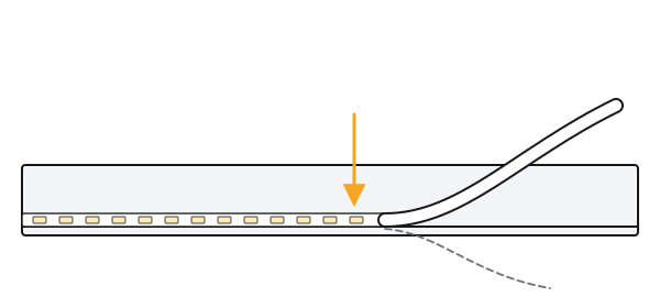
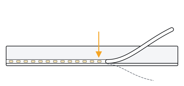
Peel and press, a little at a time.
Peel back a short length of the backing, press the strip onto the centre of the channel, and carry on. Never stretch it or fold it sharply.
-
12
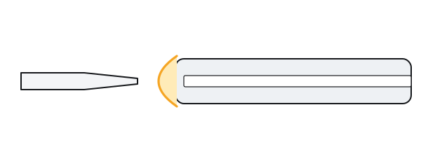
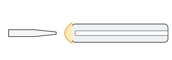
Wet areas: seal each cut end with silicone.
On a waterproof strip, fill the cut end from a silicone gun and leave it to cure for a few hours before switching on.
Stage 4 of 4 · Steps 13–15
Connect and switch on
Test it before you close the profile.
-
13
Wire the SMPS: mains in, the strip out at both ends.
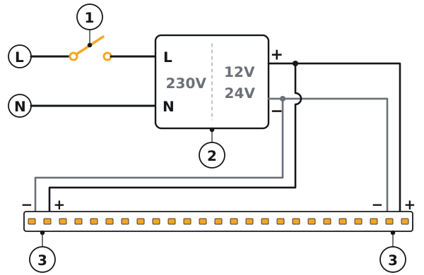
Mains to the input: the live through the switch ① to L, the neutral to N, and the earth to its terminal if the SMPS has one and the point has an earth wire. The strip to the output ②: + to +, − to −, at both ends of the run ③.
CarefulNo dimmer or fan regulator before an ordinary SMPS. Dimming needs a dimmable SMPS or a DC dimmer.
The 2-in-1 tunable-white strip is wired through its colour controller: follow the diagram that comes with it.
-
14
Switch on and look along the run.
Every section lit, and the same brightness end to end. If not, see If something is wrong.
-
15
Close it up.
Press the diffuser in along its whole length and fit the end caps, leaving a way out for the leads.
If something is wrong
Nothing lights.
Check the SMPS output with a meter: 12V or 24V. Then check + goes to + at every joint. A strip wired the wrong way round stays dark.
One section is dark.
It was cut off a mark, or a joint on its pads has cracked. Solder it again, or cut back to the last mark and join it again.
One end is dimmer.
The run is too long for one feed. Feed the other end too, or split the run.
It flickers.
The SMPS is overloaded, a joint is loose, or a dimmer sits before an SMPS that is not dimmable. Keep the load at 80% or less, solder the joint again, and dim only with a dimmable SMPS.
The strip is coming away.
The channel was not clean. Wipe it clean and dry and stick the strip again, with new double-sided tape if its own has lost its grip.
Planning a strip-light job?
Send the drawing with the runs marked, and we will come back with the strip, the profiles, and the SMPS and feed points for each run.