Spotlights, downlights, panels and step lights, set into a false ceiling or a wall. Written for the electrician on an Indian site — print it and take it up the ladder.
Mains off first.Switch off the circuit's MCB at the distribution board (DB) and prove the wires dead with a tester before touching anything.
Mains to the driver only.Most lights arrive with the driver already plugged in. Mains (230V) goes only into the driver's input. Never connect mains to the light's own lead.
Before the ceiling is boarded.Fix every light position and run every wire before the false ceiling is boarded. Give the ceiling contractor the layout and each light's cutout size.
Install to local and national electrical regulations, and only by a licensed electrician.
These are indoor lights for dry places. For a bathroom, a shower area or anywhere water can reach, check the product's rating with us first.
1
Stage 1 of 4 · Steps 1–4
Plan before the ceiling closes
Most concealed-light problems are decided before the first light arrives — when a false ceiling is boarded without a lighting layout.
1
Mark every light on the layout
Mark each position on the ceiling plan. Keep every light clear of the GI ceiling sections that carry the board: the hole must fall between two of them, never through one.
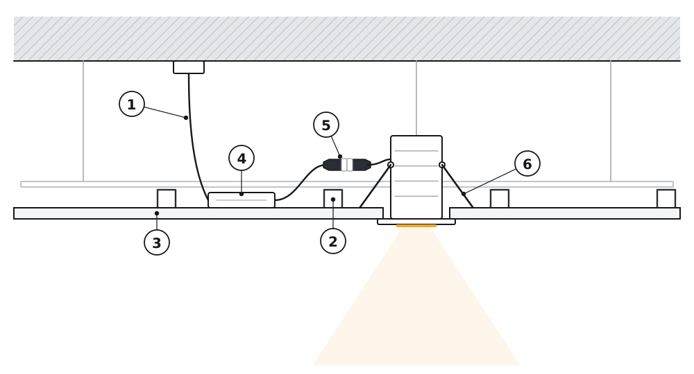
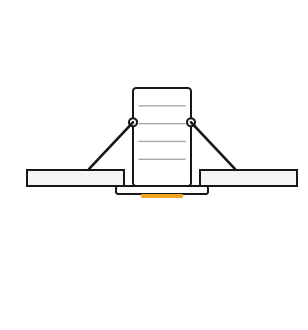
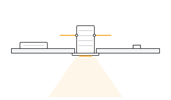
The finished job, in section. ① The cable, from the point in the slab. ② A GI ceiling section. ③ The ceiling board. ④ The driver, lying on the board. ⑤ The connector between driver and light. ⑥ The springs, holding the light to the board.
2
Check the depth
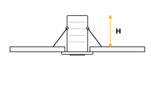
The gap above the ceiling must be deeper than the light is tall — the height is on the product page — with room left above it for air.
3
Run the wire to every point
Bring the circuit to each position in conduit before boarding, and leave enough cable at every point to reach down through the hole and be connected below the ceiling.
4
Trimless? Set the rings now
A trimless ring goes into the ceiling before the POP finish. See Trimless below.
2
Stage 2 of 4 · Steps 5–8
Cut the hole
One hole, one test fit, then the rest.
5
Mark the centres
Mark the centre of each light from the layout, and check a row of them against a straight line before any hole is cut.
6
Cut to the cutout
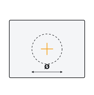
Round lights: a hole saw of the cutout size. Square and rectangular lights: mark the shape and cut it with a board saw. The trim is wider than the hole, so it covers the edge.
CarefulThe cutout for every model is on its product page and in the price list. Cut one hole and fit one light before cutting the rest — springs and clips differ between models, and ceilings differ in thickness.
7
Try one light
Fit one complete light in the first hole and check it holds tight to the ceiling. If it is loose, or will not go in, correct the size now — not after every hole is cut.
8
Clear the dust
Clean the edge of each hole and the board above it. Dust left on the board ends up on the light and the driver.
3
Stage 3 of 4 · Steps 9–12
Connect
Connect below the ceiling, where you can see what you are doing, and switch on before the light goes in.
9
Bring the wires down
Pull the point's wires down through the hole and find live, neutral and earth with a tester.
CarefulBoth colour habits are in use, often in the same building. A colour is a clue, not proof: find the live wire with a tester before connecting anything.
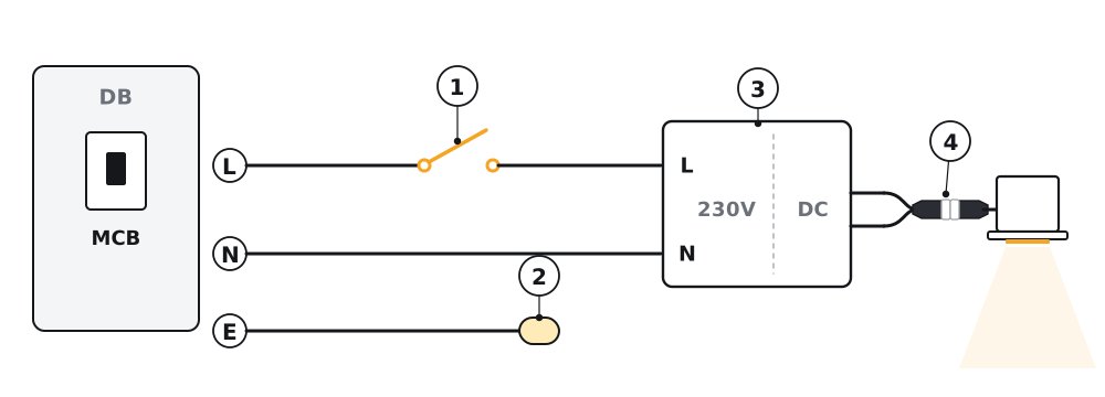
One light, two wires. ① The switch breaks the live. ② An unused earth is capped in its own connector. ③ The driver takes the mains on one side and gives the light its DC supply on the other. ④ The light plugs into the driver.
10
Mains into the driver
Connect live and neutral to the driver's input through a connector or terminal block. Cap any earth on its own — see The wiring.
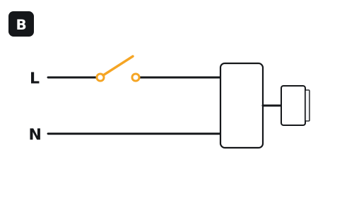
CarefulThe switch must break the live (phase) wire, never the neutral.
CarefulJoin wires in a connector or a terminal block, not by twisting them and taping them.
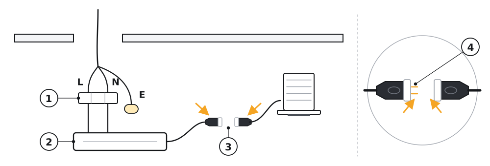
Mains to the input, light to the output. ① Live and neutral, joined in a connector. ② The driver. ③ The connector between driver and light — it goes together one way only. ④ Its moulded ends: they lock together one way round, and not the other.
11
Check the light's connector
The light joins the driver with a two-pin connector that fits one way round only. Most arrive already plugged in — check it is still pushed fully home. If it will not go together, turn it over; never force it and never cut it off.
12
Switch on and check
Switch the MCB back on and try the light now, at arm's length, before it disappears into the ceiling. Then switch off again at the MCB.
4
Stage 4 of 4 · Steps 13–16
Fit and aim
The springs do the holding. The light is pushed in, not screwed.
13
Driver first
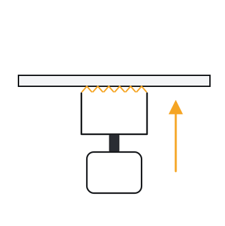
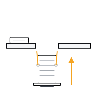
Pass the driver up through the hole and lay it flat on the ceiling board beside the hole — not on top of the light.
CarefulLeave the driver where it stays cool and can be reached: lying on the ceiling board beside the hole — not on top of the light, and not buried under insulation or debris.
14
Springs up, light in
Fold wire springs up against the body — flat spring clips fold in by themselves as the light goes through. Push the light into the hole and let go: the springs open above the board and pull the trim tight to the ceiling.
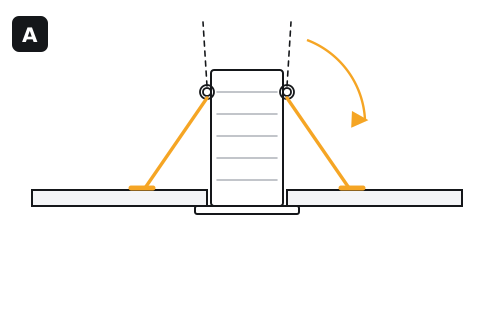
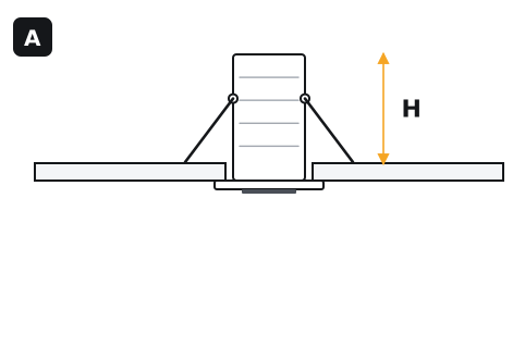
Two kinds of fixing. A · a wire spring, coiled at its pivot: fold its arm up against the body before the light goes in. B · a flat spring clip: it folds in by itself as the light is pushed through. Both open above the board and hold the light tight to the ceiling.
15
Aim adjustable lights
Tilt and turn an adjustable light by hand once it is in, with the lights on, so you can see where the beam lands.
16
Taking one out
Pull the light down gently until the springs can be reached, fold them in and ease it out. The driver comes out through the same hole after it.
Other fittings
These follow the same four stages, with one difference each.
Trimless
The ring goes in before the POP
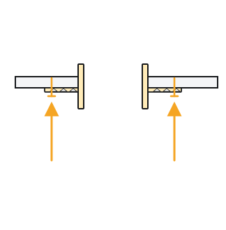
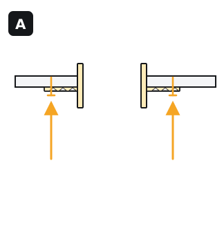
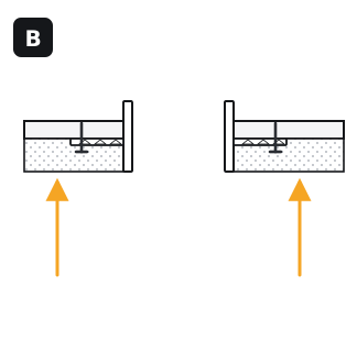
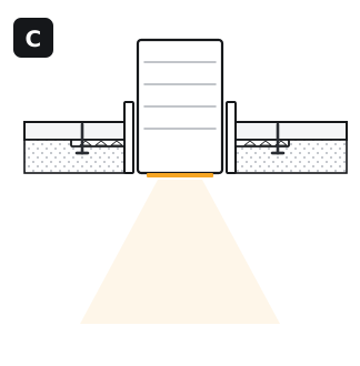
A · before the POP finish, the ring goes up into the hole and its perforated flange is fixed to the underside of the board through its holes. B · the POP is laid over the flange — the cut-outs hold it — up to the ring's lip, and painted: the ring becomes part of the ceiling. C · the light is pushed in from below at the very end.
The light can come out again later — for a repair, or for a different light — without damaging the ceiling.
BAMBOO · FARO · ZIA · POLARIS · LUX
Semi-recessed
Less depth above the ceiling
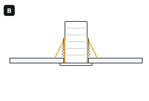
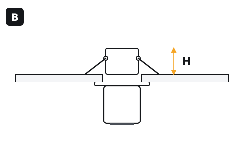
B · part of the light stays below the ceiling, so it needs less height (H) above it than a concealed light (A). It is cut, connected and fitted the same way.
ANDA · BAMBOO · ZOOM · BOLD · AURA
Grid ceiling
A 2 × 2 panel in place of a tile
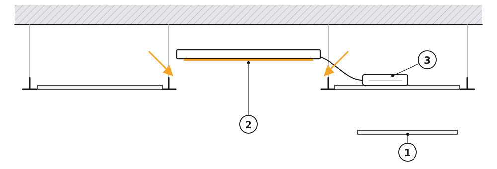
No cutting. ① Lift one tile out of the grid. ② Connect the driver, then lay the panel on the T-bars where the tile was. ③ Rest the driver on the next tile, not on the panel.
EN-DL03
Rectangular
Square to the room
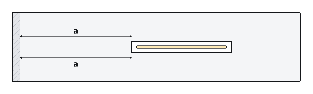
A rectangle is cut instead of a circle, to the cutout on the product page. Measure it from the wall at both ends (a = a): a rectangle a few degrees out of line shows from across the room.
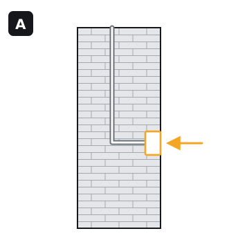
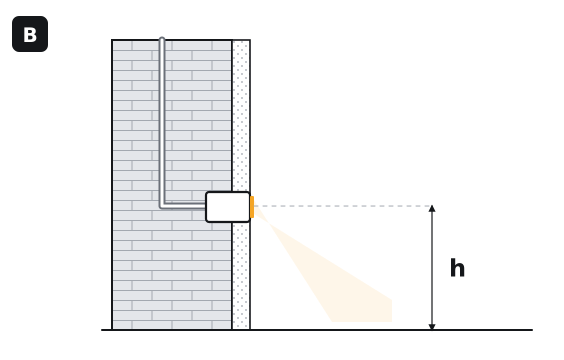
A · run conduit to each position and make the hole to the cutout, at the height (h) on the lighting drawing, before the wall is plastered. B · the light goes in after the wall is finished and painted, flush with its face. Many arrive with the driver already plugged in, like the ceiling lights.
MINI · EN-SL
If something is wrong
Five checks, in the order they usually turn out to be the answer.
One light does not light
Check its connector is pushed fully home, then the connections at the driver's input. To find the faulty part, swap its driver with the one from a working light beside it: if the fault moves with the driver, it is the driver.
Lights glow faintly or flicker when switched off
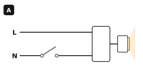
Most often the switch is breaking the neutral instead of the live — move it to the live. A switch with an indicator lamp can also leak enough current to make LEDs glow; change it for a plain switch. Long cable runs sharing a conduit with other circuits can do the same.
Lights flicker when dimmed
The dimmer and the driver do not suit each other, or the lights on the dimmer add up to less than its minimum load. Check the driver is the TRIAC version and read the minimum load on the dimmer.
Lights fail after a storm or a voltage surge
A driver takes a surge up to its rating, and no further. Where the supply is unsteady or lightning is common, fit surge protection (an SPD) at the DB.
A light keeps failing in the same place
Look at where its driver is. A driver lying on the light, or buried in insulation, runs hot and fails early. Move it to open board beside the hole.
Where the switch goes. A · on the neutral: the light can still glow when it is off. B · on the live: off means off.
Still not right? Send us a photo of the light, the driver's label and the switch, and we will work it through with you on WhatsApp.
The wiring
Three things decide it: which wire is live, what happens to the earth, and how the light is controlled.
Letter
Wire
Colours you may find
L
Live (phase)
Red — or brown in newer wiring
N
Neutral
Black — or blue in newer wiring
E
Earth
Green — or green-and-yellow
The earth wire
Most of our lights
No earth terminal
Connect live and neutral only. If an earth wire is waiting at the point, do not cut it and do not join it to neutral: put it in its own connector and fold it back into the ceiling, so it is there for whatever is fitted later.
A few products
An earth lead on the light
Some higher-wattage and outdoor lights come with a third, earth lead. That lead must be connected to earth. If the point has no earth, run one from the DB before the light is fitted.
How the light is controlled
Driver
Wires at the point
What to know
On / off
2 · L N
Any ordinary switch on the live wire.
3-in-1 colour
2 · L N
Wired like on / off. Switching off and on again moves the light to its next colour. There is no selector on the driver.
TRIAC dimmable
2 · L N
The wall switch is replaced by a phase-cut (TRIAC) dimmer on the live wire. Fit one light and try the dimmer across its whole range before fitting the rest.
DALI-2
4 · L N DA DA
Two more wires, the DALI pair, run from light to light to the DALI controller. The pair has no polarity: either wire can go to either DALI terminal. The automation contractor commissions the system.
Bluetooth mesh + RF
2 · L N
Controlled from the app or the remote. Leave the wall switch on: switching it off cuts the driver, and the app loses the light.
Planning a ceiling?
Send the ceiling plan and we will come back with the positions, cutouts and drivers, listed in the order they go up.